Continue to Site

Welcome to EDAboard.com

Welcome to our site! EDAboard.com is an international Electronics Discussion Forum focused on EDA software, circuits, schematics, books, theory, papers, asic, pld, 8051, DSP, Network, RF, Analog Design, PCB, Service Manuals... and a whole lot more! To participate you need to register. Registration is free. Click here to register now.

rusting of sensor in water by applying dc power

Status
Not open for further replies.

INGLE.SHUBHAM

Member level 1
Joined
Nov 18, 2016
Messages
34
Helped
0
Reputation
0
Reaction score
0
Trophy points
6
Activity points
303
im doing a water level controller project and This circuit works off a 12V battery or 12V AC mains The sensors are connected to the circuit at appropriate terminals. negative terminal of a power supply gnd is at the bottom of the tank, sensor terminal L is just above the bottom of the tank and sensor terminal H is at the top of the tank.

Since gnd terminal is at the bottom of the tank, when the water level falls below sensor L, and micro controller is triggered and its output goes high. As a result, the Relay energises and the motor starts filling water in the tank. The motor remains ‘on’ even when the water level crosses sensor L.

As water in the tank rises to touch sensor H, the micro controller is retriggered as a result, its output goes low. The relay de-energises and the motor stops filling water in the tank. The motor remains ‘off’ even when the water level falls below sensor H.

As water is consumed and its level falls below sensor L, the motor restarts. Thereafter, the cycle repeats.

You can also manually start and stop the motor using switch this is the concept

but im facing some of the problems here i.e due to rusting of sensors when it is drop into water
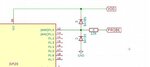
1) DC voltage when the sensor is powered with the dc voltage the circuit is working fine according to the logic but the rusting of sensor is much faster, i.e the salt like white material is accumulated on the sensor here is the ckt and the pics of the demonstrations
ca76bee5216b4d89d82b6ec7e02c41b3.jpg
sensors before connecting
IMG_20170506_101601.jpg
sensors after connecting
IMG_20170508_101755.jpg IMG_20170506_102601.jpg IMG_20170508_101726.jpg

so this is the result which i got from the above ckt, for dc voltage

2) AC voltage when the sensor is powered with the AC voltage the circuit is working fine according to the logic and there is no rusting across the sensor and here is the pics of the demonstrations for AC source
sensors before connecting
IMG_20170508_101934.jpg

sensors after connecting
IMG_20170508_101956.jpg

this is the result which i got for AC voltage


1) so my question is why the sensors are rusting in DC voltage and why not it is rusting in AC voltage and if i want to use in the dc voltage which sensors i should use so that it should not rust i want to use only metal type sensors not floating type sensor or else how i can prevent the rusting of sensors
2) if i go for the AC source i need to drop AC 12 to the water from the transformer if the transformer fails due to derating so the high vlt flows to the water which is very serious but the sensor quality will be good


so if you have any idea then please suggest to me how i can over come the above problem

THANK YOU:)
 

This is electrolytic corrosion. Basically, the water is decomposing one electrode and moving material to the other. With DC, the process is continuous but when the polarity is continuously reversed the action works for half the time in each direction and to some degree reverses itself.

The real solution is to use probes made from a more chemically resistant material, for example stainless steel, gold or even carbon.

The cheap fix is to generate the AC from the MCU but it requires some circuit changes. Instead of using one power feed and one input for each water level, you connect the power feed to one of the MCU pins and drive it with a square wave. Then remove all the transistors and connect the MCU pins directly (or through a ~10K resistor) to the sensor probes. What you do is drive the feed probe high and read the inputs (as at the moment) then drive the feed probe low and reverse the sensor pin directions so they are outputs then drive them high. As you alternate this, the probes have AC across them differentially so the corrosion should stop. Protect the MCU inputs by wiring Schottky diodes (BAT85 etc) from each input to +5V and GND. If you want to add extra protection add a resistor of say 100K from each input to ground as well.

Brian.
 
Hi,

The real solution is to use probes made from a more chemically resistant material, for example stainless steel, gold or even carbon.
I doubt this is a long time solution. I assume there is no material that can widthstand DC currents for a long time.

The only solution - like already written - is to avoid DC.

Klaus
 

Applying DC current to a pair of objects immersed in a liquid, is precisely the process of electro-plating.

If you have enough ports in your microcontroller, then it is relatively straightforward to implement the technique that Brian has outlined.

You may still want to make your electrodes of a material that will not corrode or oxidize under water. Stainless steel or nickel-plated steel are good options.
 

if i dip the 12Vac to the water directly, and after sometimes due to derating of transformer if the heavy voltage comes from the mains the whole tank contains a current then this could be dangerous
 

Hi,

* 12V is not dangerous, as long it is not inside your body.
* Nobody said you should use 12V
* you just need to avoid DC.

* you could generate any AC by toggeling a microcontroller pin...then feed it through a series connected C to avoid DC.

...or any other method to generate DC free AC.

Klaus

so i can use this waves right
VTG_ACCROSS_COLLECTOR.jpg
 

AC on ONE sensor is not enough. You need to reverse the polarity across both probes like this:

Probe A = +, Probe B = -
Probe A = -, Probe B = +
Probe A = +, Probe B = -
Probe A = -, Probe B = +

If you just pulse DC on one probe it will still corrode but at a slower rate, by alternating the probe polarities you can almost eliminate it completely.

Brian.
 

Hi,

Your scope picture is useless without voltages, timing and zero level.
And I wonder why it is no clean square wave with flat signals.
I recommend to use 50% duty cycle.

*
About Brian´s post:

* without series capacitor: you need exactely 50% duty cycle, two toggeling electrodes... and - besides the electrodes - a fully isolated tank and fluid.
* with series capacitors: duty cycle is not important. And you need to toggle only one electrode.

****
There are several ways.
I think the main question is:
Is your sensor circuit (besides the electrodes) fully isolated from tank and fluid?

Or is your sensor circuit somehow connected to the tank or pipes?
If so, it is no problem, you just need to adjust your circuit to the situation.

****

Klaus
 

This is electrolytic corrosion. Basically, the water is decomposing one electrode and moving material to the other. With DC, the process is continuous but when the polarity is continuously reversed the action works for half the time in each direction and to some degree reverses itself.

The real solution is to use probes made from a more chemically resistant material, for example stainless steel, gold or even carbon.

The cheap fix is to generate the AC from the MCU but it requires some circuit changes. Instead of using one power feed and one input for each water level, you connect the power feed to one of the MCU pins and drive it with a square wave. Then remove all the transistors and connect the MCU pins directly (or through a ~10K resistor) to the sensor probes. What you do is drive the feed probe high and read the inputs (as at the moment) then drive the feed probe low and reverse the sensor pin directions so they are outputs then drive them high. As you alternate this, the probes have AC across them differentially so the corrosion should stop. Protect the MCU inputs by wiring Schottky diodes (BAT85 etc) from each input to +5V and GND. If you want to add extra protection add a resistor of say 100K from each input to ground as well.

Brian.
upload_2017-5-9_10-6-56.png
hello sir im trying to do the ckt with AC signals for sensor and above is the sensor ckt diagram but im not understanding what is the purpose of in914 diode in the above ckt
because according to its datasheet the reverse vtg is 100v so why we need to use this diode
please tell me something about it im not understanding.
 

Hi,

the diodes is across base and emitter of the bjt and thus limits the BE reverse voltage.
I doubt the base to emitter reverse voltage is 100V

Klaus
 

I doubt the diode is necessary or would have any beneficial effect except possibly to balance the + and - currents a little.

I did a lot of tests on probes like this for a system I developed a few years ago and to be honest, I don't think capacitive coupling alone will stop the problem. It will certainly reduce it but to get best results the polarities across the probes needs to be completely reversed cyclically and also should be done with equal timing in each direction. The system I worked on used stainless steel probes and alternated 5V at a rate of about 200Hz, the speed being determined in my design by ADC conversion time. The way I did it also makes it immune to conduction to other potentials (within reason!).

Personally, I would eliminate the transistor altogether, given the high input impedance of the MCU it doesn't make sense to use a transistor and require more current to flow through the probes. Adding a resistor in series with the MCU input pin and a high value pull down will give better results for fewer components. A diode clamp between VSS and VDD can be added for extra safety if necessary. I'm thinking of say 1K to 10K in series with the probe and 100K pull-down to stop the pin floating and giving a false indication. The lower current will also extend the probe life.

Brian.
 

Don't use cheap sensors and made products. Instead use magnetic float switches. I know that some manufacturers in India you want to make lot of money manufacture these kinds of dirty products which use elctrodes and which gets easily corroded. They will make a lot of money by servicing the product and again and again using the same dirty electrodes as sensors.
 

im using a pic16f18323 to drive the motor instead of motor i have connected a leds there with a register value of 2.2K
it is 14 pin ic and i have used 6 i/p's as sensors and 2 for motor driver and 1 is open
here is the sensor ckt diagram
**broken link removed**
and the motors are driven by the transistor and relay driver circuit

power supply
V = +5V
I = 250ma

the problem im facing here is that the pic controller is heating up more when all the sensors and 1 led connected instead of motor is turned on
so please help me out how to fix this problem so that it should not heat much
 

It is saying invalid attachment.
 

I can see it OK.

Why are you using this circuit? R79 does nothing whatsoever and all the circuit does is make the probe less sensitive and need more current.
There is no way it can make the PIC heat up, your problem is is another part of the circuit or you have the PIC pin configured as an output instead of an input.

Brian.
 
@betwixt

I am still not able to view the attachment. It says invalid attachment. If it opened for you then please attach it again as an image file.
 

Like this:


I'm not familiar with the 89C2051 but if it doesn't have an internal pull-down or pull-up on the input pin, add a 100K resistor across the diode to GND to prevent the pin 'floating'.

Doing it this way reduces the current through the probe to almost nothing and allows you to reverse the probe polarity as well.

Brian.
 

Attachments

  • EDA_Pin_Protect.jpg
    EDA_Pin_Protect.jpg
    22.3 KB · Views: 58

Status
Not open for further replies.

Part and Inventory Search

Welcome to EDABoard.com

Sponsor

Back
Top