d123
Advanced Member level 5
Hi,
I'm working through the theory part of a little solar PV circuit, and wanted to ask a couple of questions before continuing with an erroneous design...
For a sweeping statement/generalisation, which of the following defines a PV panel, please:
a) A PV panel is a voltage source that develops a current based on irradiance.
b) A PV panel is a variable and finite current source, whose current is proportional to irradiance, and it develops a voltage as well.
My understanding is b).
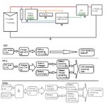
Below is the block diagram and flow chart for the circuit, is the correct "ON" flow chart b)? The load + control circuit require at least 100mA to 120mA to operate.

I've attached the schematic too, but I don't think it's needed for such general questions. (The battery charger IC can be configured for "weak" sources such as PV panels, it adjusts charge/load current accordingly, but I think I'd prefer to control the enable pin as it would be unfortunate for the op amp and voltage reference to be starved of operating current and cut out, so the whole circuit on or off - except for the op amp configured as a comparator, which needs to be on all the time - but not somewhere inbetween seems the best option based on what I need it do.)
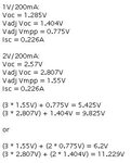
The following are the calculations I've done for what I may expect from the little hobby panels - until I can actually get outside during the day to measure them, based on a sticker on a proper panel (I'm (un)professional to the last...), I contacted the panel maker and they have no Isc, Voc, Mppt chart for either panel, ..., the only info. I have to go on is 2V/200mA and 1V/200mA. Only as a general rule of thumb answer, do those numbers look realistic approximations for what are probably not high efficiency PV panels - "toy" panels?

Also, I assume a 250mA fuse between panels and electronics would be suitable?
This has me stumped - so the Isc current doesn't reach the electronics what are suitable current limiting blocks, please? I read you can fry your equipment if you do not bear this in mind.
Thanks.
I'm working through the theory part of a little solar PV circuit, and wanted to ask a couple of questions before continuing with an erroneous design...
For a sweeping statement/generalisation, which of the following defines a PV panel, please:
a) A PV panel is a voltage source that develops a current based on irradiance.
b) A PV panel is a variable and finite current source, whose current is proportional to irradiance, and it develops a voltage as well.
My understanding is b).
Below is the block diagram and flow chart for the circuit, is the correct "ON" flow chart b)? The load + control circuit require at least 100mA to 120mA to operate.

I've attached the schematic too, but I don't think it's needed for such general questions. (The battery charger IC can be configured for "weak" sources such as PV panels, it adjusts charge/load current accordingly, but I think I'd prefer to control the enable pin as it would be unfortunate for the op amp and voltage reference to be starved of operating current and cut out, so the whole circuit on or off - except for the op amp configured as a comparator, which needs to be on all the time - but not somewhere inbetween seems the best option based on what I need it do.)
The following are the calculations I've done for what I may expect from the little hobby panels - until I can actually get outside during the day to measure them, based on a sticker on a proper panel (I'm (un)professional to the last...), I contacted the panel maker and they have no Isc, Voc, Mppt chart for either panel, ..., the only info. I have to go on is 2V/200mA and 1V/200mA. Only as a general rule of thumb answer, do those numbers look realistic approximations for what are probably not high efficiency PV panels - "toy" panels?

Also, I assume a 250mA fuse between panels and electronics would be suitable?
This has me stumped - so the Isc current doesn't reach the electronics what are suitable current limiting blocks, please? I read you can fry your equipment if you do not bear this in mind.
Thanks.