Continue to Site

Welcome to EDAboard.com

Welcome to our site! EDAboard.com is an international Electronics Discussion Forum focused on EDA software, circuits, schematics, books, theory, papers, asic, pld, 8051, DSP, Network, RF, Analog Design, PCB, Service Manuals... and a whole lot more! To participate you need to register. Registration is free. Click here to register now.

[SOLVED] dealing with Harmonics ( fc/2, 3fc/2)

Status
Not open for further replies.

BMR

Member level 5
Joined
Jan 28, 2010
Messages
82
Helped
10
Reputation
20
Reaction score
9
Trophy points
1,288
Location
Sweden
Activity points
1,824
Hello all,

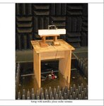
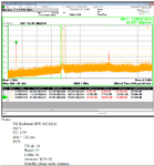
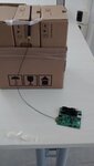
I'm dealing with low power module at 2.4 GHz. The design is based on Ti's cc2538+cc2592. In conductive testing all the harmonics seems to be attenuated very well. But in radiated testing with an antenna, there seems to be high levels of fc/2 and 3fc/2 ( 1.2 GHz and 3.6 GHz ). The antenna used is a commercial rubber ducky antenna. The antenna is connected to a coax cable and the cable to module via pigtail connector. The module is programmed to transmit at +21 dBm. If I change a different ducky antenna, fc/2 is still present but the levels are well below the FCC limit. The customer doesn't want to change the ducky antenna because of the budget.

so, has anybody dealt with fc/2 and 3 fc/2 harmonics? Any suggestion on how to set traps for fc/2?

Thanks!
 

Most probably the helical antenna (rubber-duck) that you use, have some higher gain at harmonic frequencies.
A thing that you can do is to use an extra low-pass matching network (series L, shunt C) to feed the antenna.
If you need extra harmonics rejection you can use two matching cells (series L, shunt C, series L, shunt C).

As you can see from the attached figure, a good filter network is already in place. The issue is LPF shows good attentuation at 2nd, 3rd, 4th and 5th, but how do you construct a trap for 1.2 GHz? The Fc is at 2.4 GHz. EM simulation of S21 shows 0.2 - 0.3 dB loss at 1.2 GHz and 2.4 GHz which is a typical response. Probably a notch filter at 1.2 GHz may do the trick, but with other rubber-duck antenna the levels of 1.2 GHz are attentuated very well.

For a comparison sake,
rubber-duck-1 ( customers antenna)- 1.2 GHz shows -11 dBm EIRP
rubber-duck-2 ( My antenna)- 1.2 GHz shows -69.23 EIRP

Also, Channel 11 (2405 MHz) with the customers antenna has no fc/2, but channel 18 (2440 MHz) has fc/2.

Does anybody think the coax cable in conjuction with antenna is causing this?


Debug_imahe1.png
 

I'm surprised that the transmitter emits n*fc/2 subharmonics at all. I don't believe that it used frequency doubling internally.

When you say it's not present in conducted test, is there any spur at fc/2 at all, even at a very low level? Can it be provoked by output mismatching in the conducted test? If not you may consider an effect of transmitted RF picked up somewhere in the circuit. You should also ask TI support if the device has the capability to generate fc/2 signals.
 

I'm surprised that the transmitter emits n*fc/2 subharmonics at all. I don't believe that it used frequency doubling internally.
Indeed it's hard to believe, but the radiated results says otherwise.

Do you still think the transmitter is responsible for f/2?

When you say it's not present in conducted test, is there any spur at fc/2 at all, even at a very low level?

The conducted tests spectrum is crystal clear. It matches well with my EM simulated results.

What does't correlate is conducted and the radiated measurements. My angle of view is, the antenna impedance @ 2.4 GHz is not even close to 50 Ohms ( typically 50-60 Ohms is fine).

What if I place a BPF( mulitlayer ceramic RF BPF) near the antenna µfl connector which has a good attentuation at 1.2 GHz?

I have the FCC test report of ti's transceiver+Pa module, doesn't show anything at f/2.
 

Probably Incident Wave returns back to the transmitter when this "bad" antenna is connected and the transmitter starts to mix-up with other stuffs.
 

Provided the transmitter doesn't use frequency doubling (I'm rather sure that it's not the case), there must be an active circuit which is falling into sub-harmonic operation, e.g. caused by reflected power.

I would test if the PA has the capability by applying variable reflection factor between +/- 1. There's also a certain possibility that radiated RF is picked up by the circuit due to bad layout. What happens if the output can e.g. cross talk into the PA RX/TX control line?
 

I would test if the PA has the capability by applying variable reflection factor between +/- 1.

Load pull analysis shows that, BOM ( w.r.t filter topology+ PA) is quite stable for all the loads.

There's also a certain possibility that radiated RF is picked up by the circuit due to bad layout. What happens if the output can e.g. cross talk into the PA RX/TX control line?

Yes, that's a high possibility and in that case I have to go for a new layout( Which is a big issue, because we have to go for a fresh certification again and it costs a lot). I have to test the Ti's evaluation board with the same nightmarish antenna.
 

If susceptibility of the board is the problem, screening or RF absorber material might be able to handle it.

Also, if you can identify an offended circuit node, placing a filter capacitor could be a solution below full redesign.

I once experienced a problem with a 433 MHz radio where a free wheeling diode somewhere on the board picked up RF and re-radiated second harmonic above accepted level.
 
  • Like
Reactions: BMR

    BMR

    Points: 2
    Helpful Answer Positive Rating
The antenna used is a commercial rubber ducky antenna. The antenna is connected to a coax cable and the cable to module via pigtail connector.

Can you share a photo of the bad antenna setup? This antenna type usually needs an external ground of sufficient size at the antenna feed. Connecting with a cable, with no suffient grond plane at the antenna itself, might cause trouble. Poor VSWR + lots of RF on the cable shield. Ferrite bead might be worth a try then.
 

Can you share a photo of the bad antenna setup? This antenna type usually needs an external ground of sufficient size at the antenna feed. Connecting with a cable, with no suffient grond plane at the antenna itself, might cause trouble. Poor VSWR + lots of RF on the cable shield. Ferrite bead might be worth a try then.

I have attached Radiated tests and it's setup. I also tried the ferrite beads, with this particular antenna doesn't seem to work.

I have a very primitive setup at my lab, just for a clear picture.

- - - Updated - - -

If susceptibility of the board is the problem, screening or RF absorber material might be able to handle it.
I have some microwave absorbers and I will try wrapping it around coax and antenna.

Also, if you can identify an offended circuit node, placing a filter capacitor could be a solution below full redesign.
This is the only solution I thought off initially but I'm afraid it will compromise the output power and I don't have enough Pout headroom. Anyways I have ordered some ceramic filters which I intend to put close to the ufl connector.

Thanks for the suggestions
 

Attachments

  • setup.jpg
    setup.jpg
    70.9 KB · Views: 93
  • radiated_test.png
    radiated_test.png
    69.7 KB · Views: 93
  • IMG_20170505_114706018.jpg
    IMG_20170505_114706018.jpg
    162.6 KB · Views: 78

So the (failing) measurement is done with the metal ground underneath the antenna (first photo)?
If yes, that setup gives different f/2 levels with the different antennas?

The second photo lacks ground for the antenna ... is this a testcase, or just to show the components?
 

So the (failing) measurement is done with the metal ground underneath the antenna (first photo)?
If yes, that setup gives different f/2 levels with the different antennas?

Yes, the same setup with a different antenna shows no f/2 or negligible levels. But the antenna shown in first photo corresponds to the tests results. The Strange thing is channel 11( 2405 MHz) is clean, but channel 18 (2440 MHz) has this issue. I still haven't checked the channel 25( 2480 MHz).


The second photo lacks ground for the antenna ... is this a testcase, or just to show the components?
You are right, it lacks grounding for the antenna. This is just to show the components.
 

Just to check if the problem is related to antenna matching, can you insert a 3dB attenuator at the antenna feedpoint?
 

Unfortunately my receiver antenna's gain and sensitivity is too bad that I don't see the f/2 in my lab spectrum analyser. I have to try that in our test house next week. Any test suggestions in conducted mode I can do it right away.
 

For conducted tests, I agree with FvM's test proposal: "Can it be provoked by output mismatching in the conducted test?"
Given that the issue is seen at selected frequencies only, you might want to check with different coax length to vary the reflection phase.
 
  • Like
Reactions: BMR

    BMR

    Points: 2
    Helpful Answer Positive Rating
I forgot about the coax length which can vary the reflection phase. Some time back altering the coax length did solve the problem with sub-harmonics.

Thanks!
 

Varying the coax length changes both the phase of reflected wave through the cable but also tunes the parasitic cable antenna. You could try to suppress the common mode wave down the cable screen by placing a ferrite tube around the cable and check if it changes anything.
 

I did place some ferrite beads around the cables and the response was the same. But as you say altering the length tunes the antenna as well. Will post response asap.
 

For conducted tests, I agree with FvM's test proposal: "Can it be provoked by output mismatching in the conducted test?"
Given that the issue is seen at selected frequencies only, you might want to check with different coax length to vary the reflection phase.

Ok. So, I varied the length of the coax cable from 49.5 cms( original length which was used in the anechoic chamber) to 50.5 cms. The f/2 disappeared with 50.5 cms. All 3 channels are clear.
 

Status
Not open for further replies.

Part and Inventory Search

Welcome to EDABoard.com

Sponsor

Back
Top