E-design
Advanced Member level 5
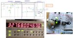
I recently came up with this unusual design for a 32768 Hz crystal oscillator.
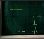
It uses the reverse breakdown of an NPN transistor with a timing cap and resistor as an oscillator. I found that using a crystal as shown, I can lock the frequency quite accurately.
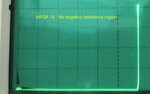
The two green LED's act as some temperature compensation. I also tried red ones, but the compensation was not adequate. When tested in a lab oven from 0-40° C it only drifted about 0.4 Hz. The crystal was nothing special, like $1 for a bag of 10 eBay special. Not all common NPN types work in this circuit. I tested a MPSA18 low-noise audio transistor, with no success. Looking at the breakdown curve on a curve tracer also showed no noticeable negative-resistance region.
I constructed the first three stages on an IC socket, but later cut out the NPN to try other types. That is the device hanging on the side in the picture.
The counter was locked to the lab Rb. GPS frequency standard during the tests. I am not sure if any type of these crystals will work in the circuit. More tests needed.
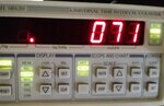
The 1 sec jitter also averaged under 100 pS as shown.
P1 is a 10 k pot.
It uses the reverse breakdown of an NPN transistor with a timing cap and resistor as an oscillator. I found that using a crystal as shown, I can lock the frequency quite accurately.
The two green LED's act as some temperature compensation. I also tried red ones, but the compensation was not adequate. When tested in a lab oven from 0-40° C it only drifted about 0.4 Hz. The crystal was nothing special, like $1 for a bag of 10 eBay special. Not all common NPN types work in this circuit. I tested a MPSA18 low-noise audio transistor, with no success. Looking at the breakdown curve on a curve tracer also showed no noticeable negative-resistance region.
I constructed the first three stages on an IC socket, but later cut out the NPN to try other types. That is the device hanging on the side in the picture.
The counter was locked to the lab Rb. GPS frequency standard during the tests. I am not sure if any type of these crystals will work in the circuit. More tests needed.
The 1 sec jitter also averaged under 100 pS as shown.
P1 is a 10 k pot.