Continue to Site

Welcome to EDAboard.com

Welcome to our site! EDAboard.com is an international Electronics Discussion Forum focused on EDA software, circuits, schematics, books, theory, papers, asic, pld, 8051, DSP, Network, RF, Analog Design, PCB, Service Manuals... and a whole lot more! To participate you need to register. Registration is free. Click here to register now.

Lifetime of electrolytic capacitor with very little ripple current in it?

Status
Not open for further replies.
T

treez

Guest
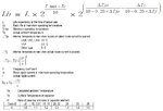
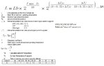
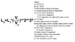
According to the 23rd page of the linked (below) electrolytic capacitor app note, equation 2-19 means that if a capacitor had virtually zero ripple current in it, then its rated life would only be twice what its life would have been if it had had rated ripple current in it for the specified time (eg 3000 hrs etc).
This cant be right. What is wrong with equation 2-19?

General Descriptions of Aluminum Electrolytic Capacitors , Nichicon...
https://www.nichicon.co.jp/english/products/pdf/aluminum.pdf
 

This is a related post to the above, so i put it here.

Hello,

Long post, but please only skim read and I beg you to shovel any answer you think may have any relevance whatsoever (even if it doesn’t) , to this horrendous subject of pinning down the actual lifetime of radial leaded electrolytic capacitors………

Our investors want us to write them a report on the lifetime of “Wet” Aluminium Electrolytic Capacitors in our product. (60W offline flyback, 110-265VAC input)

The electroytic capacitor we are using is the Acon KL series 400V, 100uF one. (as attached)
This is the capacitor that our Chinese designers put in our product. (Post rectifier capacitor)

The Chinese designers sent us the attached lifetime calculation for this capacitor.
The strange thing is, in this formula, if one decreases the ripple current value flowing in the capacitor, then the lifetime decreases!!!....

….This can’t be right, does anyone know what’s gone wrong here? And is there any other formulae for radial leaded electrolytic capacitors lifetime?
As you can see, the Chinese capacitor lifetime equation lists a parameter called “delta(Tj0)”…
This parameter is the “internal temperature rise when rated ripple current is applied”.
Strangely, they don’t tell us what this value [“delta(Tj0)”] is for the Acon KL series capacitor…..instead, their lifetime equation simply gives “delta(Tj0)” values for the Rubycon USR, USC & USG series capacitors. –But that’s not what we are using, so why do they state it?

Also, another parameter used in the attached lifetime equation is called “alpha”. It is the “ratio of the case top and core of the capacitor element”. From the attached lifetime exerpt, you can see that the lower the diameter of the capacitor body, the greater the temperature of the capacitor case gets. Is this typical for other electrolytic capacitors too?...it doesn’t seem to make sense…..because surely the deciding factor is how long the capacitor body is?....that is, longer body capacitors would run hotter as its further from the internals to the base…the base being where most heat transfers out of the capacitor?

Anyway, why does our Chinese designers lifetime equation give a lower lifetime when the capacitor has less ripple current in it? Have I missed something?

Also, why does no radial electrolytic capacitor manufacturer give thermal resistance values from internal core to the case for their capacitors?..it is impossible to actually do a lifetime calculation without this information.
 

Attachments

  • Electrolytic capacitor lifetime.jpg
    Electrolytic capacitor lifetime.jpg
    90.6 KB · Views: 166
  • Acon KL capacitor.pdf
    89.1 KB · Views: 111
Last edited by a moderator:

This post is again related to the above, and is calculating Electrolytic capacitor lifetime....or would be if the equation supplied by Rubycon wasnt giving out garbage numbers.....
None of the Electrolytic capacitor lifetime equations supplied by any of the electrolytic capacitor manufacturers seem to work....is this deliberate?....is it to try and stop people being able to do their own lifetine equatiions so they cant design their own power supplies and therefore cant compete in this arena?

Anyway, Hello......
I am trying to do a lifetime equation for the Rubycon TXW, 450V, 100uF Radial Leaded Electrolytic capacitor.
(ripple current (I) = 0.54Arms; Ambient temp = 85degC)

However, the lifetime equation provided by Rubycon (linked below) is giving garbage numbers.
Rubycon capacitor lifetime equation…..(equation 4.7)….
**broken link removed**

When you make out an excel spreadsheet for equation 4.7, then if you reduce the ripple current in the capacitor (I), then the lifetime reduces!!!...this makes no sense.
Do you know what’s going on?
I have provided here my Excel spreadsheet of the equation 4.7

Rubycon TXW series datasheet (100uF, 450V capacitor)
**broken link removed**


The equation 4.7 seems to give better numbers when a really low ESR is used. (say less than 0.1 ohms). However, the ESR of the 100uF, 450V capacitor is 3.32 ohms at 120Hz…..this high value of ESR gives nonsense values for lifetime.
Even with sub 0.1 ohm values of ESR, the lifetime equation gives out silly numbes for lifetime…..for example, when you put a really low value of ripple current in, the lifetime hardly reduces at all.
It just doesn’t make sense?
Do you know a proper Rubycon capacitor lifetime equation?

The equation 4.7 is not said to work at all for delta_Tj values above 20……this is ridiculous as that’s exactly where it calculates out to...
 

Attachments

  • RUBYCON CAP LIFETIME_Equation 4.7.zip
    8.3 KB · Views: 129

Also, another parameter used in the attached lifetime equation is called “alpha”. It is the “ratio of the case top and core of the capacitor element”. From the attached lifetime exerpt, you can see that the lower the diameter of the capacitor body, the greater the temperature of the capacitor case gets. Is this typical for other electrolytic capacitors too?...it doesn’t seem to make sense…..because surely the deciding factor is how long the capacitor body is?....that is, longer body capacitors would run hotter as its further from the internals to the base…the base being where most heat transfers out of the capacitor...

Let me try: for the same capacitance, with the same technology (and ratings), a tall and slim capacitor has larger surface area compared to a fat and round one. The larger surface area helps to keep the inside temp lower (don't ask me how much because I do not know). For some strange reasons (perhaps you know better than me) fat and short capacitors are more commonly found in most power supply filter stages.

Coming to the point you mentioned, alpha is (delta ts)/(delta tc) and decreases for fat caps. You consider a simple case: inside is hot and the outside is cold (alpha will be small) and the shape will be one in which the heat has to travel longer distance radially (fat ones). For slim (and tall; will be called beautiful if the caps were human) ones, the core and surface temp will be closer and alpha will be greater.

The report is written in nipponese english and you need to read it twice!
 
  • Like
Reactions: treez

    T

    Points: 2
    Helpful Answer Positive Rating
The equation 4.7 seems to give better numbers when a really low ESR is used. (say less than 0.1 ohms). However, the ESR of the 100uF, 450V capacitor is 3.32 ohms at 120Hz…..this high value of ESR gives nonsense values for lifetime.
Where did you get the ESR number? It obviously contradicts the ripple current specification as the calculated > 70K temperature rise with rated current reveals. Either one or the other specification is wrong.

You probably overlooked a comment, that the calculation isn't valid for > 30 K temperature rise.

Garbage in -> garbage out.
 
  • Like
Reactions: treez

    T

    Points: 2
    Helpful Answer Positive Rating
Ahh, hang on, Post #2 is now sorted, their equation has incorrectly swapped the "L" and the "Lb" values.
However, even with that correction, it would be nice to know how they calculated the delta_Tj0 value (the internal temp rise when rated ripple current is flowing).
Also, with post #2, if i put in 1mA of ripple current (into the corrected equation) at 85degC ambient, then i only get 3.4 years of life, is that right, it sounds very low for a capacitor with virtually no ripple current in it.

- - - Updated - - -

Where did you get the ESR number?
It is from (Dissipation Factor * Xc) = 0.25 * 1/(2.pi.120.100u)
 

Capacitor lifetime is a function of core temperature. If you are assuming 85°C ambient temperature and no ripple current, you get the lifetime of the respective capacitor type for 85°C core temperature.
 
  • Like
Reactions: treez

    T

    Points: 2
    Helpful Answer Positive Rating
so if a 5000hrs, 105degC Electrolytic capacitor is stored at 85degC , then it will be dead after 20000 hours (approximately 2 years of storage)?

- - - Updated - - -

Also, equn 4.7 (top of 2nd page) of this...

Rubycon capacitor lifetime equation…..(equation 4.7)….
**broken link removed**

Has an expression "(Tmax - Ta)" in the equation........should this not be "(Tmax - Tc)"?

where...
Tmax = max ambient allowed
Ta = Actual ambient temperature
Tc = Case surface temperature of the capacitor.

- - - Updated - - -
 
Last edited by a moderator:

Depends on the lifetime specification. If the specification is for Tmax and rated ripple current (as assumed in equation 4.7), the lifetime without ripple is respectively higher.
 
  • Like
Reactions: treez

    T

    Points: 2
    Helpful Answer Positive Rating
Hello,
Sorry, more problems with the lifetime equation in post #2 above, which is also attached here (please remember that they got “L” and “Lb” the wrong way round)

The attached excel exerpt shows that as the value of core temperature rise due to ripple current (delta_Tj) goes above the temperature rise when rated ripple current flows (delta_Tj0) , then the lifetime equation will go negative!!
Also, if either of the temperature rise expressions becomes equal to 40 degC, then the lifetime equation fails because of “divide by zero”.
Do you know what is the significance of these factors?

Also, when the core temperature rise due to ripple current (delta_Tj) goes above 40 degC, then the expession involving temperature rises always equals about 1.45, no matter how much hotter the core temperature rise due to ripple current goes. This can be seen in the attached.
Do you know what is the significance of this?
 

Attachments

  • Electrolytic capacitor lifetime.jpg
    Electrolytic capacitor lifetime.jpg
    90.6 KB · Views: 225
  • Electrolytic capacitor lifetime_bad.jpg
    Electrolytic capacitor lifetime_bad.jpg
    212.4 KB · Views: 142
Last edited by a moderator:

Also, if either of the temperature rise expressions becomes equal to 40 degC, then the lifetime equation fails because of “divide by zero”.
The application note instructs you not to use the equation for ΔTj>20K.

If ΔTs (rated ripple current temperature rise) comes even near to 20K, you are using unrealistic capacitor data.

- - - Updated - - -

Here's a lifetime versus ambient temperature and ripple current diagram for a 105°C HV Epcos/TDK capacitor (Series B43888). You see that the calculated temperature rise for rated ripple current (Iac,r) is below 5K.

Lifetime.png
 

Thanks, yes i often tried to put Epcos into products, but was always told they are too expensive, and the leads times too long.
In truth they arent that much more expensive than the nichicons and rubycons of this world, but the lead time is an issue.

- - - Updated - - -

Also, the Electrolytic capacitor lifetime equation in post #2 above is from a document that concerns the Akon KL series Radial Electrolytic capacitor. So therefore, why , in the exerpt shown in post #1, do they give “delta_Tj0” example figures from the Rubycon "snap-in" series capacitors? (USR, USG, USC & VXP)

"Snap-in" capacitors endure far less internal temperature rise than Radial Electrolytics, so therefore why have they not given figures for Radial Electrolytics?.......After all, in the SMPS that they designed for us, they put in a Radial Electrolytic, the Akon KL series.

As you know, “delta_Tj0” is the internal temperature rise of the capacitor which happens when rated ripple current is flowing in the capacitor.
 

Can you confirm that the load life quoted at the top of an electrolytic capacitor datasheet, is simply the life with zero ripple current in it, at the maximum ambient temperature?

Eg for the Rubycon BXC series datasheet, it would last 8000 hours if stored at 105 degC....(obviously with zero ripple current in it).

Rubycon BXC series datasheet
https://www.rubycon.co.jp/en/catalog/e_pdfs/aluminum/e_bxc.pdf

- - - Updated - - -

Woops , in post #10 it should be the attached calculation for the second term in the lifetime equation

- - - Updated - - -

Hello,

This is related to the above so please may i put it here if its ok, though it is a separate new post

Attached is the equation for electrolytic capacitor lifetime.
It was provided to us by our Chinese SMPS designer.
According to this equation, as delta_Tj0 increases, so too does lifetime.
That doesn’t make sense…..if the internals were getting hotter, then lifetime should get less.
Can you say that this equation is incorrect?

- - - Updated - - -

This is related to the above so please may i put it here?

Hello,
Page 16 of this Panasonic document gives an overly simplistic equation for electrolytic capacitor lifetime calculation….

Panasonic electrolytic capacitor app note:-
**broken link removed**

I actually used to work for Panasonic. We used to make consumer goods branded Panasonic. We used to use all Panasonic’s own electrolytic capacitors in the products we made. We used to have full-featured lifetime equations for each family of Panasonic electrolytic capacitors. These were provided by the Panasonic management. However, Panasonic do not make these equations public. Why not?
Do you agree that really getting to the bottom of electrolytic capacitor lifetime, for any individual family of radial leaded electrolytic capacitors is impossible?
After all, the big companies that make these electrolytic capacitors probably have allegiances to big electronics companies who demand that full featured lifetime equations are kept secret?
Do you agree?
 

Attachments

  • Ripple decreases life of electrolytic.jpg
    Ripple decreases life of electrolytic.jpg
    218.6 KB · Views: 118
  • Electrolytic lifetime equation.jpg
    Electrolytic lifetime equation.jpg
    98.7 KB · Views: 193

Can you confirm that the load life quoted at the top of an electrolytic capacitor datasheet, is simply the life with zero ripple current in it, at the maximum ambient temperature?

No, the lifetime is usually specified for rated ripple current. At zero ripple current, the lifetime might be e.g. about 40 percent higher (assuming 5 K temperature rise at rated ripple current).

According to this equation, as delta_Tj0 increases, so too does lifetime.
That doesn’t make sense…..if the internals were getting hotter, then lifetime should get less.
You are reading the equations wrong. Lb and ΔTj0 are both determined by the capacitor design. ΔTj0 is e.g. 5K for the capacitor series under discussion.
 

You are reading the equations wrong. Lb and ΔTj0 are both determined by the capacitor design. ΔTj0 is e.g. 5K for the capacitor series under discussion.

Thanks, the thing is, supposing you have two electrolytic caps which are basically the same, except one has 10 degrees internal temp rise with full rated ripple, and the other has 5 degrees temp rise with full rated ripple current…...
……well then you would expect the one with just 5 degrees temp rise to be longer lasting….but that does not happen…..the attached excel sheet proves that…..if you put in the lower temp rise in the blue square you see the lifetime decrease, which doesnt make sense.
I think the equation is wrong. Surely?

The attached exel uses the equation given in post #13
 

Attachments

  • EL CAP LIFETIME.zip
    7.5 KB · Views: 72

You are comparing capacitors with 8000h lifetime at core temperatures of 110 and 115°C at rated ripple current. Below rated ripple current, the "10K" capacitor has higher temperature margin and thus longer lifetime, above rated ripple current, the effect is opposite.
 
  • Like
Reactions: treez

    T

    Points: 2
    Helpful Answer Positive Rating
Thanks, the thing is , why is it that no Radial electolytic capacitor datasheet actually gives the internal temperature rise of the capacitor when it has rated ripple current flowing in it?......without this information, it is absolutely impossible to do a proper lifetime calculation....unless you are lucky enough to get one of those capacitors with a thermocouple built into it..or the capacitor datasheet gives you the Heat radiation factor of the capacitor, so that you can work out the internal temperature rise from the case temperature rise.....but again, that data is never in the datasheet.

Just imagine if a power fet datasheet didnt tell you the theta(jc).....it would be ridiculous.
Is this all about industrial secrecy or something i wonder?

Rubycon BXC series...
https://www.rubycon.co.jp/en/catalog/e_pdfs/aluminum/e_bxc.pdf

- - - Updated - - -

The way i always do it (lifetime calculation) is to assume a value of alpha as in the exerpt already shown.
Alpha is the ratio of internal temperature rise to top surface temp rise.
You can measure top surface temp rise, and then with the assumed value of alpha, you calculate internal temp rise...then from that you can calculate the internal temp rise with rated ripple current.
But this assumes a value for alpha....which is usually said to be a value of about 1.2 for 18mm diameter radial electrolytics.

- - - Updated - - -

Do you know which is the best of the attached radial electrolytic lifetime calculators to use?
The illinois capacitor one means you have to assume internal temperature rise with rated ripple is 5 degrees...whereas the other means you have to assume the rario f the internal temp rise to the case surface temp rise is 1.2 for an 18mm diam capacitor.

So which assumption is safest?

By the way, in our application, the Illinois one gives us 39000 hrs, whereas the China Electronics one gives us 29000 hrs lifetime....for the same cap in the same situation.
 

Attachments

  • Electrolytic lifetime equation_from China.jpg
    Electrolytic lifetime equation_from China.jpg
    98.7 KB · Views: 135
  • illinois capacitor lifetime equation.jpg
    illinois capacitor lifetime equation.jpg
    47.5 KB · Views: 128

I agree that it's impractical and prone to wrong conclusions if you need to guess the ΔTj0 assumed in the capacitor ratings. As for the Rubycon capacitors, the value is however clearly stated in the quoted application note, 5K for most standard series, 3.5K for snap-in types.

I guess that most manufacturers will apply a similar general scheme.
 
  • Like
Reactions: treez

    T

    Points: 2
    Helpful Answer Positive Rating
Thanks,
the following rubycon el cap app note
**broken link removed**

..only tells you the "heat radiation factor"...but doesnt tell which family of caps this is for.....so you would have to measure the top case surface and assume alpha = whatever for the diameter of cap chosen.
I wondered if anyone knows how expensive it is to get a capacitor made with a thermocouple in it for say rubycon radial el caps?

- - - Updated - - -

***********************************************************************
Hello,
Please may I put this related_to_the_above post here?
The attached electrolytic capacitor lifetime equation gives nonsense lifetime values for values of internal temperature rise above 40 degrees. Due to the denominator of (10 – 0.25 * T)
This seems bizarre..after all, you could have a 105degC capacitor operating in a 10 degree ambient environment, and it could have a 40 degree internal temperature rise, which takes its core to 50 degrees….this is still well below its rated 105 degC oprating temperature……so what is so bad about a 40 degree internal temperature rise for an electrolytic capacitor?
 

Attachments

  • Electrolytic lifetime equation_from China.jpg
    Electrolytic lifetime equation_from China.jpg
    98.7 KB · Views: 113

Isn't the page stating 5K temperature rise for "other series" being published by Rubycon?

5K is obviously a standard value for general purpose electrolytic capacitors, you also find it e.g. in the Panasonic application note. I don't understand why you are continuing to guess the value?

- - - Updated - - -

Why are you harping on about the (10 – 0.25 * ΔT) denominator? It's an approximation of the empirical observed behavior for a limited temperature range up to 20K. It becomes inaccurate far below 40K.
 
  • Like
Reactions: treez

    T

    Points: 2
    Helpful Answer Positive Rating
Status
Not open for further replies.

Part and Inventory Search

Welcome to EDABoard.com

Sponsor

Back
Top