Continue to Site

Welcome to EDAboard.com

Welcome to our site! EDAboard.com is an international Electronics Discussion Forum focused on EDA software, circuits, schematics, books, theory, papers, asic, pld, 8051, DSP, Network, RF, Analog Design, PCB, Service Manuals... and a whole lot more! To participate you need to register. Registration is free. Click here to register now.

Boost DC-DC Converter system time constant

Status
Not open for further replies.

julian403

Full Member level 5
Joined
Feb 28, 2014
Messages
254
Helped
1
Reputation
2
Reaction score
1
Trophy points
18
Location
Argentina
Activity points
2,105
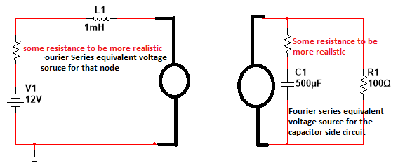
Hello, I have to analize the boost dc-dc converter.

Captura.PNG

This has two operation mode. One when the transistor is on and second when transistor is off.

When transistor is on, in the first mode. The ecuation is:

\[ V = {r}_{on} {i}_{1}(t) + L \frac{d {i}_{1}(t)}{dt}\] where \[{r}_{on} = 0.01 \Omega \]

And the second mode it's

\[ V + L {{i}_{1}}^{0-} = L \frac{d {i}_{2}(t)}{dt} + R {i}_{2}(t) + \frac{1}{C} \int {i}_{2}(t) dt + \frac{{{i}_{2}}^{0-}}{C}\]

The problem here is the initial condition \[{i}_{1}^{0-}\] and \[{i}_{2}^{0-}\]of the diferential ecuation which it's growing until it reaches to the permanet condition.

How many step I must consider? because there is two times constants. One for the first mode's circuit and other for the second mode's circuits. For the firts mode circuit the time constant is L/r_on and for the second mode's circuit is ≈ Π/(RC) that's because it's a second order's system.

I need to know that for example if there is the need to know if the circuit is a continouos current or discontinouos current.
 

There's no increasing average current in DCM mode because the current returns to zero, thus the ton phase is not varying.

I'm not sure if it's of much use to calculate a CCM solution for constant duty cycle, in a real boost converter the duty cycle will be more likely feedback controlled, e.g. voltage controlled with peak current limit.
 
Thanks and I notice that the second differential equations is wrong. There must be a equation system.


The equation of the second mode is

\[ 12 = L \frac{d {i}_{1}(t)}{dt} + \frac{1}{C} \int {i}_{1}(t) dt - \frac{1}{C} \int {i}_{2}(t) dt\]

\[0 = \frac{1}{C} \int {i}_{2}(t) dt + {i}_{2}(t) R-\frac{1}{C} \int {i}_{1}(t) dt\]

\[ \left[\begin{array}{ccc}{12 }\\{0} \end{array}\right] = \begin{bmatrix}{L \frac{d}{dt} + \frac{1}{C} \int dt }&{- \frac{1}{C} \int dt}\\{ \frac{1}{C} \int dt }&{\frac{1}{C} \int dt + R}\end{bmatrix} * \left[\begin{array}{ccc}{{i}_{1}(t) }\\{{i}_{2}(t) \end{array}\right] \]

- - - Updated - - -

Sorry but I want to analize the CCM mode
 
Last edited:

Current and voltage will reach steady state at different times. What is clear is that the current will reach steady state before the voltage does due to very low resistance in the inductor equivalent circuit (using fourier series).


Voltage will reach steady state at a time higher or equal to 50 ms. Less than 50 ms is impossible.

I am basing myself in the fact that the Fourier series equivalent voltage source in the inductor circuit will switch between 2 states (1 state which will increase the voltage at that node and another state with 0 V) periodically and the same for the Fourier series equivalent voltage source in the Capacitor circuit which will go up in voltage during the charge, and down during the discharge. ESR of capacitor is needed in order to avoid an ideal voltage source across a capacitor.
 
Good analysis! How can I or what it's the equation for the voltage source for example the circuit whit the capacitor and the resistor load? I thinks that is

\[\frac{12[V]}{s} + L {i}^{(0-)} \]

and for the voltage source in series whit the resistor and inductor it's \[- L {i}^{(0-)}\]

by the way \[ L {i}^{(0-)}\] is the initial condition and I used the laplace's transform
 
Last edited:

How come I am unable to see the equations properly? They are apparently jpeg(s) cut and pasted from some latex files? I am using firefox but there should be no problems with jpeg images?
 

I must confess, I don't get the exact purpose of the calculation. The converter startup goes over a few CCM cycles, then changing to DCM.

Due to the non-linear nature of the circuit, you need to iterate through the individual cycles to determine the actual current waveform.

If you are only interested in the time constant for reaching steady state, the 50 ms RC time constant gives a rough estimation. The boost converter in DCM is however sourcing 12V + constant power, which partly reduces the effective time constant. Thus settling to 90% of steady state voltage will be shorter than 2.3 time constants, e.g. 1 to 1.5.
 
Status
Not open for further replies.

Similar threads

Part and Inventory Search

Welcome to EDABoard.com

Sponsor

Back
Top