Continue to Site

Welcome to EDAboard.com

Welcome to our site! EDAboard.com is an international Electronics Discussion Forum focused on EDA software, circuits, schematics, books, theory, papers, asic, pld, 8051, DSP, Network, RF, Analog Design, PCB, Service Manuals... and a whole lot more! To participate you need to register. Registration is free. Click here to register now.

How to synchronize 2 different signal?

Status
Not open for further replies.

myjoe1026

Junior Member level 3
Joined
Jan 7, 2016
Messages
26
Helped
0
Reputation
0
Reaction score
0
Trophy points
1
Activity points
198
Hi all,

Is there any way to synchronize 2 signal with different frequencies?
i.e. the first rising edge should be at the same time.

Thanks a lot.
 

You're asking two different things:
1) Synchronize 2 signals
2) First rising edge should be the same.

Which is it?

If you are trying to SYNCHRONIZE two signals, you can use any number of synchronizers, e.g., 2-flip-flop synchronizer, etc.
But, I'm not sure what you mean by "the first rising edge should be at the same time". If event "A" occurs before event "B", then you could latch "A" and then clock it out with "B". I think you need to be more specific.
 

You could synchronize the two rising edges at one point in time, but not all all the edges obviously, since the two signals are at different frequencies.
So what, exactly, do you want?
 

You could synchronize the two rising edges at one point in time, but not all all the edges obviously, since the two signals are at different frequencies.
So what, exactly, do you want?

Thank you all and sorry for the misunderstanding.

Yes, I would like to synchronize the two rising edges at one point in time.
 

So how are these two signals being generated?

They are generated by 2 different PCBs. One is 1MHz, the other is 6MHz. They have slight phase difference. I'd like to synchronize them to see a period 1MHz signal with 6 periods of 6MHz signal and add them together with summing amplifier.
 

Unless the signals are derived from the same master clock, they'll also show a frequency difference, respectively varying phase difference.

It's not clear yet which information is carried by the signals. "Rising edge" (post #1) suggests digital signals, "add them together with summing amplifier" makes only sense for analog signals. In the latter case, digital synchronization methods as previously discussed aren't applicable.
The "Rising edge" I mentioned is because the 2 signals are square waves, they'll have rising and falling edges.
 

Unless the signals are derived from the same master clock, they'll also show a frequency difference, respectively varying phase difference.

It's not clear yet which information is carried by the signals. "Rising edge" (post #1) suggests digital signals, "add them together with summing amplifier" makes only sense for analog signals. In the latter case, digital synchronization methods as previously discussed aren't applicable.

- - - Updated - - -

O.K., square waves. What could be the purpose of summing them?

- - - Updated - - -

I keep the reservation mentioned before. If both signals don't have exactly same frequency (= derived from a common master clock), continuous synchronization isn't possible, respectively involves phase jumps.
 

The only way to synchronize two different frequencies is to have:

-one of the frequencies to be the "master". Usually the higher frequency.
-then by using counters, divide down the the lower frequency.

That way you'll not only ensure that the phase relationship remains, but that one frequency is an integer multiple of the other.
 

Sorry about the double post above.

Here's another possible approach:
Use a D Flip-Flop with the 1MHz clock going to the D input and the 6MHz clock going to the CLK input.
The FF Q output is then the 1MHz clock with its rising (and falling) edge synchronized to the 6MHz rising edge (differing only by the FF clock to output delay).
This assumes a positive clock edge triggered FF such as the HC4013 or HC74.

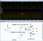
LTspice simulation below:

Capture.PNG
 
Last edited:

Sorry about the double post above.

Here's another possible approach:
Use a D Flip-Flop with the 1MHz clock going to the D input and the 6MHz clock going to the CLK input.
The FF Q output is then the 1MHz clock with its rising (and falling) edge synchronized to the 6MHz rising edge (differing only by the FF clock to output delay).
This assumes a positive clock edge triggered FF such as the HC4013 or HC74.

LTspice simulation below:

View attachment 138314
This is a classic recipe for metastability. DON'T DO IT!
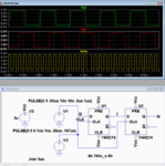
 

To minimize any effect of metastability you can use the two flip-flips in the 74HC4013 or 74HC74 package in series (simulation below).
Thus even if the first flip-flop becomes metastable, it likely will be cleared before the second flip-flop changes state.
The only change in the signal is that the 1MHz signal is delayed by an extra clock-pulse, but that shouldn't be a factor in this application as the edges are still coincident.

Capture.PNG
 

Status
Not open for further replies.

Part and Inventory Search

Welcome to EDABoard.com

Sponsor

Back
Top