Continue to Site

Welcome to EDAboard.com

Welcome to our site! EDAboard.com is an international Electronics Discussion Forum focused on EDA software, circuits, schematics, books, theory, papers, asic, pld, 8051, DSP, Network, RF, Analog Design, PCB, Service Manuals... and a whole lot more! To participate you need to register. Registration is free. Click here to register now.

short circuit problem

Status
Not open for further replies.

Enzy

Advanced Member level 1
Joined
Mar 20, 2016
Messages
488
Helped
2
Reputation
4
Reaction score
2
Trophy points
18
Activity points
4,607
I am designing a circuit and for some reason I am confused on how not to short the output.


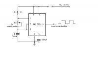
at pin 3 of the 555 timer if I connect it to the gate of a N-Channel FET and the source of the fet to GND I dont think I could directly add a positive dc voltage to the drain of the FET since that would short out.

My aim is to gain a higher voltage and also to switch the higher voltage at high frequency, so would I have to add a coil in series with the drain of the fet then apply the positive dc to the coil?
 

Most Mosfets need 10V pulses on the gate. The load for an N-channel Mosfet is connected between its drain pin and a positive high voltage that will not zap the drain pin.
But I think you are talking about making a voltage boost converter that has a coil and a diode.
 

555 timer doesn't have the strength to drive any decent
sized power FET.

Many cheap ways to get a square pulse train, if square
is all you want. You could even self-oscillate a center
tapped transformer with two NPNs and two resistors,
if you just want high voltage and don't care much
about efficiency.

The 555 is beloved because you can do so many
things with it, but that doesn't mean it's the best
at any of it.

I have digital FET's which take 5v to activate and I am getting 11.8v output from pin 3 of the 555, isnt that more than enough to properly activate a fet even if its not a digital fet.

- - - Updated - - -

Most
But I think you are talking about making a voltage boost converter that has a coil and a diode.

I have been battling with different circuits trying build and test which one is better to use. I just need 30khz doesnt matter the waveform it should be adjustable and I should be able to increase voltage if needed 12v and above my fets are 55v max so thats my limit for now.

- - - Updated - - -

I have a couple chips like 4060, 556, 555, 4017 and 4047 I was thinking about using a 4047 and building a basic inverter circuit but I am searching the datasheet for the chip but I cannot find how high of a frequency it can produce.
 

Status
Not open for further replies.

Similar threads

Part and Inventory Search

Welcome to EDABoard.com

Sponsor

Back
Top