Continue to Site

Welcome to EDAboard.com

Welcome to our site! EDAboard.com is an international Electronics Discussion Forum focused on EDA software, circuits, schematics, books, theory, papers, asic, pld, 8051, DSP, Network, RF, Analog Design, PCB, Service Manuals... and a whole lot more! To participate you need to register. Registration is free. Click here to register now.

Open collector comparator pulling up to higher voltage than the pullup voltage..

Status
Not open for further replies.
T

treez

Guest
Hello,
We are using a TS391ILT open collector comparator.
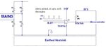
Its Vdd is 14V
Its output has a 33k pullup to 3V3, and the output goes to a microcontroller input. This microcontroller is supplied by the same 3V3 that the output pulls up to.
On the noninverting input pin we have an 8V3 reference voltage.
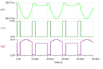
On the inverting input pin we have a square wave which has a frequency of 10ms and goes from zero volts to 13V.
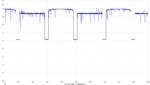
At the output of the comparator, when the output should be pulled up to 3V3…it is instead pulling up to about 3.9V.
Do you think this is due to leakage current from the Vdd pin to the output pin?
Why does the datasheet not mention it?

How high would you expect this leakage current to go with ambient temperature rise to say 85degC?

TS391 datasheet....
https://www.st.com/content/ccc/reso...df/jcr:content/translations/en.CD00001660.pdf
 

Actually, the data sheet DOES mention output leakage current, but only where VCC and output voltage are the same. But if you read even more of the data sheet, you'll note that you're exceeding the input common mode range.
 
  • Like
Reactions: treez

    T

    Points: 2
    Helpful Answer Positive Rating
Hi,

The mentioned current has the same direction as output_low_current.

***
I assume as long as negative supply of the comparator is properly connected to a valid supply (either GND, or negative),
It makes no sense that the output is driven to 3.9V.
Unsolder the comparator and check outputvoltage again, to verify that it's really the comparator that drves the output higher than the 3V3.

Klaus

The data sheet specifies a maximum of 1uA output-high current. BUT, that's for a specific condion when VCC and output votages are equal; with an 11 volt differential, that current could be much higher. But, as I said, I would fix that common-mode issue and see if that resolves the problem.
 
  • Like
Reactions: treez

    T

    Points: 2
    Helpful Answer Positive Rating
thanks, do you really think the common mode issue is going to create the leakage current issue?.
 

Hi,

I don´t think so.
****

According datasheet specification.
Yes it is specified as OUTPUT current.
But the IOL is specified as output current, too. And the value in the datasheet has the same sign.

In my eyes it is not possible according the condition "V_out = VCC" that the current is flowing from VCC in direction output.
If both pins have the same voltage, then there is no current flow possible.
Therefore my assumption that the current flow if from OUT to GND (-VCC).

With the specified value one can calculate the max pull up resistor value for a minimum V_OUT_HIGH voltage.

Klaus
 
  • Like
Reactions: treez

    T

    Points: 2
    Helpful Answer Positive Rating
According to the datasheet, the operation conditions are not violating the common mode specification. Vcm is usually defined as (Vp + Vn)/2. The datasheet explicitly mentions that one input can even swing above the positive rail.

There's no specification for "sourcing" output leakage, Vo = Vcc is obviously referring to "sinking" leakage current. Considering the fact that the output pin (as well as the inputs) has no clamp diode to Vcc, the leakage current shouldn't exceed the nA range.

The observed pulling above 3.3V may be caused by a defective TS391 or a completely different hardware problem.
 

According to the datasheet, the operation conditions are not violating the common mode specification. Vcm is usually defined as (Vp + Vn)/2. The datasheet explicitly mentions that one input can even swing above the positive rail.
The input common mode range is specified as VCC-1.5 (VCC-2 over temperature). For the quoted case, that would be 12.5V, but the OP states that he's driving 13V. It's not going to damage anything, but it's not a good design. But, yes, that probably doesn't explain his problem.
 

Thanks, why is it a problem that out inverting input is going above the input common mode range.....might the output rail to the wrong rail?....As you know, its a comparator , so that is the worst case scenario...but surely that wouldnt happen?

- - - Updated - - -

The observed pulling above 3.3V may be caused by a defective TS391 or a completely different hardware problem.

...i think you could well be right....

The scope shot of the comparators output is attached here.
You can see it pulling up to 3.9V. Actually, I am now more noticing that it only alternately pulls up to 3.9V. Every 10ms it alternates from “Normal” 3v3 otuput, then to “abnormal” 3v9 output. The circuit is grounded to the full wave bridge rectified mains, with no isolation. The PCB is sitting on an earthed heatsink. (on a thin thermal pad).
In other words, the circuits ground is “Neutral” for 10ms, and then it is the negative going “Live” for the next 10ms. (due to the way a full wave bridge rectifier connected to the mains operates) As you know, “Neutral” is approximately earth potential.
I am now thinking that there is some kind of capacitive coupling between the comparator and the earthed heatsink, and that whenever the circuit ground is on that half cycle that represents the negative going live wire, then there is some interaction which makes the comparator’s output go to 3.9V.
Have you come across this before?
Maybe indeed this is not a leakage problem at all.
 

Attachments

  • Comparator output voltage.jpg
    Comparator output voltage.jpg
    151.6 KB · Views: 162

Here is a schematic of the situation.
 

Attachments

  • Open collector comparator_1.jpg
    Open collector comparator_1.jpg
    51.3 KB · Views: 166

I have no ambitions to explain the difference between input voltage and common mode voltage further. It's particularly relevant for comparators with large differential input voltage. Refer to literature.

Regarding the reported measurements, the oscilloscope waveform obviously can't be explained with the repetitive input waveform sketched in post #10. Looking at the real waveforms might help to understand the effect.

Capacitive coupling could be, but waveform details when exceeding 3.3V doesn't suggest it. Anyway, if you're worried about the voltage excursion, place a schottky clamp.
 
  • Like
Reactions: treez

    T

    Points: 2
    Helpful Answer Positive Rating
Thanks, just ran it with no earthing of the heatsink and still get the problem, so it cant be what i thought in my post #9
 

The "schematic" appears like the old LM339, but is not necessarily
entirely factual (see ideal current sources; what else may be
obscured or elided?).

I suspect that this modern "open collector" comparator may not
be truly "open" (i.e. no pad connection except the collector of a
lonely low side switch transistor). IC product design norms have
come to include ESD protection which a bare output transistor is
unlikely to meet - many of my old timey designs sure fell short of
the claimed 1500V and so I suspect there may be an undocumented
ESD protection network of some sort.

Thus there may be some potential for charge pumping, back-leakage
and so on. Though I would not expect this to drive a 33K resistor
to a steady +0.6V - that's some uA and no protection structure
ought to leak like that. But the spec for IOH is constrained to VOH=VCC
and makes no claims about ESD diode (if any) leakage as a result.

Given the specificity of the IOH spec, test escapes or continuing
production of highly leaky product could happen. Have you tried
another part, and have you tried an output I-V curve pull on a
normal (and so-behaving) part to see whether IOH has a
sourcing signature when VOH<VCC?
 
  • Like
Reactions: treez

    T

    Points: 2
    Helpful Answer Positive Rating
TS391 is 1/4 LM339. O.C. output has either no or more likely a zener diode protection, won't source current either. Even if there would be some leakage current sourced, which can't be excluded according to a strict datasheet lecture, it's surely not several 10 µA like the reported apparent leakage, rather a few nA.
 

Thanks, we are reading this osvervoltage with a TA041 diff probe, and we wonder if it has problems with common mode input range.

TA041 diff probe
https://www.farnell.com/datasheets/2207207.pdf?_ga=1.149010102.1679746183.1489787856

- - - Updated - - -

I tried adding Common mode choke to AC input of circuit , but that doesn’t solve it and just makes the signal look more noisy.
Strangely the signal looks less noisy when the PCB is raised away from and above the earthed heatsink.
The PCB itself has no earth connection.
Strangely, when the pcb is sitting on the heatsink (with separator pad), the signal looks less noisy when heatsink is disconnected from earth.

Though whether it looks more noisy or not, the overvoltage every other mains cycle on the comparator output is still there. I changed the pullup from 33k to 2k7 and the overvoltage goes down from 3.9V to about 3.45v

I think a battery scope may be needed to see if this isnt some measurement artifact.?
 

You may have a ground problem shifting according to a mains half cycle.

I can reproduce the effect by moving the ground tied to rectified mains on every 2nd half cycle.

So I suspect that somehow the way you are connecting things up moves the ground up and down. No idea how this happens in your case. It is for you to figure out. It was difficult enough setting this up in the simulator!
 

Attachments

  • GND_prob.png
    GND_prob.png
    19.4 KB · Views: 120
  • Like
Reactions: treez

    T

    Points: 2
    Helpful Answer Positive Rating
You might try floating the 'scope with an isolation transformer
(or breaking off the ground prong on the cord) to see if it is
a ground loop or ground getting kicked by a bad neutral bond.
 

Mentioning floating ground and differential probe usage earlier would have obsoleted most of this discussion...

The differential probe has 4 MOhm ground impedance. Current injected into the 10 k load resistance by common mode voltage can fully explain the apparent leakage current, as pointed out by E-Design.

Common mode range of the high voltage differential probes is in contrast a thing you can rely on.
 
  • Like
Reactions: treez

    T

    Points: 2
    Helpful Answer Positive Rating
Thanks,
So by connecting the diff probe to the comparator output, we have effectively connected a 4 megohm resistor from Earth (ie neutral) to the 33k pullup resistor?

This pattern of seeing anomolous voltages every alternate 10ms must be quite common when using diff probes?....at least where impedances of measured nodes is high.
 

Status
Not open for further replies.

Similar threads

Part and Inventory Search

Welcome to EDABoard.com

Sponsor

Back
Top