Continue to Site

Welcome to EDAboard.com

Welcome to our site! EDAboard.com is an international Electronics Discussion Forum focused on EDA software, circuits, schematics, books, theory, papers, asic, pld, 8051, DSP, Network, RF, Analog Design, PCB, Service Manuals... and a whole lot more! To participate you need to register. Registration is free. Click here to register now.

Questions regarding flyback arrangement. help Needed

Status
Not open for further replies.

horizonrays

Newbie level 3
Joined
Apr 22, 2017
Messages
4
Helped
0
Reputation
0
Reaction score
0
Trophy points
1
Activity points
48
calculate how.pngexplain please.png

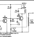
my first question is that what does 1/3 t1 10 turns in the transformer do ?

what is the function of c5 0.02 capacitor , which is at base and connects with the coil ?

snubber capacitor c6 .47, what is the formula to calculate it ?


how to calculate the value of c1, c2, c3.
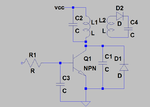
i have seen many circuits where capacitor is used with diode. why to have diode and capacitor together ? Either capacitor or diode is alone capable enough as snubber are they not ?

why to have snubber c2 in paralel to l1, when transistor already have snubber diode ?

what is the function of c3 which is in between base and ground ?
 

Hi,

I'm not familiar with this circuit.
But I assume this is a self oscillation circuit. And the 1/3 t1 10 turns is the feedback to generate the oscillation.

There will be other users that can tell you more about the curcuit.

Klaus
 

Ito doesnt show dots on coils so its had to say, but id say this is kind of like a royer converter, the 470n acts to staunch the otherwise ruinous magnetising current if its a forward, and to staunch the leakage spike if its a flyback.
But yes , its self oscillating, and the lower coil turns off the transistor when its current builds up beyond the level decided.
 

neither is self oscillating circuit, both are driven from ne555 or other better pwm circuits.
the one with t1 is high voltage circuit, probably producing 5-10kv
 

1. 1/3 means there are 3 coils for transformer 1.primary 2. secondary 3.auxiliary.

2. https://www.digikey.com/en/articles...c-snubber-design-for-power-switches?WT.srch=1
please find the design in above link.

Now when the transistor turn off the the transform de energises and the current continues to flow in transformer. When this happens the voltage on the collector gets high and that can damage the transistor.

Inorder to avoid this a diode is placed. But when heavy load are used the voltage will be very high, so to remove this energy an RC oscillator is used. This energy is dissipated in the Resistor which needs to be with very high power handling say 1W-10W depending on the application

Some tips: Please place the snubber as close to the transformer as possible.

Thanks
 

neither is self oscillating circuit, both are driven from ne555 or other better pwm circuits.
How do you know? Post #1 clarifies that you don't understand the circuit operation well.

In fact, the 10 turns windings makes only sense if it provides positive feedback. Unless blocked by Q1, the circuit will also self oscillate, can be however synchronized by an external pulse generator.

The Ltspice schematic has no feedback and depends on external pulse generator. Many details are questionable, e.g. effectively parallel C1 and C2, useless D1. Purpose of C3?
 

eht.jpg
schema2.jpg
tesla.jpg
what.jpg

First of all, thanks to all.
Learned remembers, I am just a hobbyist, I do not know much about electronics. I am here to learn, I hope you will consider this and will overlook my mistakes.
I am very much interested in High Voltage Projects which produces sparks, I have built some circuits. They worked fine. So I decided to learn more about their workings. I came across things which I did not know.
Since I could not find answers on google, hence I am asking here.

@treez what is the difference between staunch and and resonance capacitor, are they same? Some where I read that it is resonance capacitor.

@FvM schematic is theoretical schematic, many circuits seems to use use c1 and c2. I know they act as snubber, but I do not know when to use them and when not to.
I have asked in my question what is the function of c3?

LTSPICE schematic one is just a theoretical circuit with all possible components which can be employed.
I used that schematic to ask the question when to use a component and when not to and how to calculate their value.

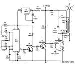
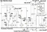
I have included some circuits for consideration , please have a look.
in the schematic one a capacitor is placed between ground and base. I do not know the use of this capacitor nor do I know how to calculate it.

A diode and a capacitor is placed in between ground and collector, I know they act as snubber, but I do not know how to calculate the value of capacitor.

In Schematic 2, a diode is placed in between base and ground, what is the function that diode ?

In schematic 3 a capacitor is place across transformer, I do not know what is proper term for this capacitor, resonant capacitor , or snubber capacitor or something else or how to calculate it.
Flyback circuits use RCD snubber in general to mitigate the problems created by parasitic capacitance and leakage inductance.

Schematic 4, is the complete schematic that I have used after cropping in my question before.
 

Hi,

Schematics 2 a diode is placed inorder to avoid the negative spikes on the base of transistor.

how does the diode between collector and gnd act as a snubber? you need to provide a diode between collector(anode of diode ) and red dot of transformer (cathode).
https://www.youtube.com/watch?v=c6I7Ycbv8B8

Please watch the above video for better ubderstanding.


"In schematic 3 a capacitor is place across transformer, I do not know what is proper term for this capacitor, resonant capacitor , or snubber capacitor or something else or how to calculate it.
Flyback circuits use RCD snubber in general to mitigate the problems created by parasitic capacitance and leakage inductance."

For all the flyback transformer, there will be leakage inductance.


thanks
 

@rohithkrishnan I already have seen that video.
thanks for your answers.
 

Status
Not open for further replies.

Similar threads

Part and Inventory Search

Welcome to EDABoard.com

Sponsor

Back
Top