Continue to Site

Welcome to EDAboard.com

Welcome to our site! EDAboard.com is an international Electronics Discussion Forum focused on EDA software, circuits, schematics, books, theory, papers, asic, pld, 8051, DSP, Network, RF, Analog Design, PCB, Service Manuals... and a whole lot more! To participate you need to register. Registration is free. Click here to register now.

[SOLVED] Brushed DC Motor Control Power stage design

Status
Not open for further replies.

abc_de

Full Member level 5
Joined
Jan 9, 2014
Messages
243
Helped
11
Reputation
22
Reaction score
11
Trophy points
1,298
Location
Ludhiana ਪੰਜਾਬ
Activity points
2,939
Hello
i want to control the speed of my DC Brushed Motor
Ratings are given below:

voltage: 31 v
amperes: 3.8 amp
Watt: 80

i have not work on DC motor control. please suggest me driver circuit,switching Modulation and other consideration things.
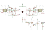
i am following Microchip AN893 app notes.
 
Last edited:

Hi,

I recommend to look at your distributor for motor driver ICs.
They come with built in pretection circuit. They usually are rugged and easy to use.

Or look directely at the IC manufacturers internet site. Usually they have selection guides to find the best suited IC.

Klaus
 

ok.
i am thinking for LMD18245 Driver IC for design but its too expensive. therefore i am planning for driving motor with external MOSFET and Driver.
my question: is Brushed DC motor required circuit like bootstrap capacitor in power stage. my DC voltage is 37v From SMPS and i have to spin motor maximum at 28V
 

Hi,

What about L6203?
Do you need to change direction?

Klaus
 
  • Like
Reactions: abc_de

    abc_de

    Points: 2
    Helpful Answer Positive Rating
HI
yes it seems useful and less expensive them LMD18245 driver but without current protection. but for this driver how i can choose right Cboot value for pwm: 4khz-20khz
 

Hi,

but for this driver how i can choose right Cboot value for pwm: 4khz-20khz
Just follow the recommendation in the datasheet.

Klaus
 

For dc motor control by change in pwm duty cycle we can get different speed. How we keep torque constant.
 

Torque is controlled by armature current, not its voltage (which governs speed).

If you want to limit the torque to a constant value, you require some form of armature current feedback.
 
  • Like
Reactions: abc_de

    abc_de

    Points: 2
    Helpful Answer Positive Rating
Yes, as long as you measure the current for both legs of the H-bridge. Which leg will be active depends of course on the motor's rotation direction.
 
  • Like
Reactions: abc_de

    abc_de

    Points: 2
    Helpful Answer Positive Rating
Your rated motor current is 3.8 amps, which will provide 100% torque.

If you limit the current to half that (1.9 amp), you get 50% torque,

If you limit the current to 10% of that (0.38 amp), you get 10% of the torque.
And so on.
 
  • Like
Reactions: abc_de

    abc_de

    Points: 2
    Helpful Answer Positive Rating
Hi,

In post#9 you talk about IGBT .... it will be less efficient than Mosfet.

H-bridge (single) GND leg current is not necessarily motor current.
In slow decay mode there is motor current, but no GND leg current.

For torque control and/or speed control I recommend to use slow decay mode.
I recommend a true motor current measurement - shunt in series to motor.

Klaus
 
  • Like
Reactions: abc_de

    abc_de

    Points: 2
    Helpful Answer Positive Rating
hello
i do not have experience of DC motor control algorithms. presently i am running my motor in uni direction applying 30% duty cycle to high side mosfet of leg A and permanent on low side mosfet of leg B during motor run command. Fpwm IS 8khz.

i have one more question when motor run then amplitude of voltage is not sable its just like a wave. what is reason behind this but it should be constant i guess.

for bootstrap operation i am using 10ohm resistor in series with UF4007 and capacitor is 3.3uf/63V.

please suggest me

https://www.silabs.com/tools/Pages/bootstrap-calculator.aspx

i have found this like for bootstrap cal. but i do not know IDD0 how i can cal.

- - - Updated - - -

one more thing
in motor control i need only uni directional then to break motor only slow decay is sufficient ?
 
Last edited:

Hi,

applying 30% duty cycle to high side mosfet
This means "fast decay", which gives very weak RPM.

--> for slow decay you should switch between LOW_side and HIGH_side.

****
amplitude of voltage is not sable its just like a wave
show us a picture. Many possible reasons.

***
for bootstrap operation i am using 10ohm resistor in series with UF4007 and capacitor is 3.3uf/63V.
Why 10 Ohms? Is it in the datasheet?
No need for 63V. 20V usually is enough.
What circuit are you talking about.

***
i do not know IDD0 how i can cal.
press HELP: -->Driver output-side quiescent current from driver data sheet (mA)
This is IDD0.
Show us exactely your complete circuit...

***
Read abut decay modes.

Klaus
 

yes sure very shortly will up date my software according to slow decay for Current Re circulation current.

here is bootstrap circuit for high side mosfet.
z4f4Q.png
 

Hi,

here you showed ANY circuit witjout device names, withoutv values, but I asked about YOUR circuit.

Klaus
 

please check circuit which I am using
driver.png

- - - Updated - - -

this is picture of current after filter when motor spin without load
IMG20170429173347.jpgIMG20170429173435.jpg

- - - Updated - - -

picture of measureable current IMG20170429173123.jpg

- - - Updated - - -

this is picture when motor is under load and move load like mechanical cam...

IMG20170429172813.jpg
 

Hi,

Very interesting... you ask for help but it takes 18 posts to show that you use IR2112 with IRF640...you never mentioned this before.
Then you complain about voltage waveform... but don't show us.
Then you talk about a filter but don't show us.
Then you talk about IGBT, but there is none in your circuit.

I asked for complete and your circuit, but just give confusing incomplete informations.

Klaus
 

hi
this is almost complete circuit except microcontroller section and current sense signal conditioning circuit.
in my #14 post I talk about amplitude of waveform (may be unclear information). before that discussion was different.
I apologize for less and unclear information

- - - Updated - - -

here is circuit include filter and amplifier circuit
driver.png

- - - Updated - - -

this is picture of unfiltered current of h bridge
IMG20170429172408.jpg
 

Attachments

  • driver.png
    driver.png
    38.2 KB · Views: 113
Last edited:

Status
Not open for further replies.

Similar threads

Part and Inventory Search

Welcome to EDABoard.com

Sponsor

Back
Top