Continue to Site

Welcome to EDAboard.com

Welcome to our site! EDAboard.com is an international Electronics Discussion Forum focused on EDA software, circuits, schematics, books, theory, papers, asic, pld, 8051, DSP, Network, RF, Analog Design, PCB, Service Manuals... and a whole lot more! To participate you need to register. Registration is free. Click here to register now.

voltage doubler and application

Status
Not open for further replies.

rajaram04

Advanced Member level 3
Joined
Jun 17, 2012
Messages
871
Helped
6
Reputation
12
Reaction score
5
Trophy points
1,298
Location
earth
Activity points
7,687
hello all

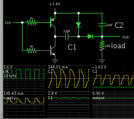
is the imge for voltage doubler is ok ?

is it applicable to designer a cell pjone charger with 3.7v battery followed by 5v zener etc ?

VoltageDoubler.gif
 

Hi,

Not sure, just read circuit has several limitations, one being 555 current limit of 200mA; another being timer Vout is always 1 - 2V below V+ (3.7V * 2) - ~2V... - and the load influences that; also, charge diode-capacitor pumps are weak current-wise. I breadboarded a voltage inverter and a doubler with a timer and diode-caps months ago out of curiosity and I doubt I would use either in a real application, especially one that required more than a few mA, but each to their own preferences. Give it a go in a simulator or breadboard it and find out if it's suitable for the circuit needs. Have you seen the version using a complementary pair on the timer output? There's also a version that parallels two timers outputs to "double" the voltage.
 
A cell phone has a charger circuit in it that has a 5VDC USB input and charges the "3.7V" lithium battery cell to 4.20V. A voltage doubler is not used.
A 555 was used as a voltage doubler about 30 or 40 years ago. The voltage was not doubled, instead it was increased only a little.
A voltage boost converter circuit using a Mosfet and an inductor is used today, but not as a battery charger, it can be used to boost the 3.7V from a lithium battery cell in a power bank to the 5VDC USB used to feed the charger circuit in a cell phone.
 
Hi,

Not sure, just read circuit has several limitations, one being 555 current limit of 200mA; another being timer Vout is always 1 - 2V below V+ (3.7V * 2) - ~2V... - and the load influences that; also, charge diode-capacitor pumps are weak current-wise. I breadboarded a voltage inverter and a doubler with a timer and diode-caps months ago out of curiosity and I doubt I would use either in a real application, especially one that required more than a few mA, but each to their own preferences. Give it a go in a simulator or breadboard it and find out if it's suitable for the circuit needs. Have you seen the version using a complementary pair on the timer output? There's also a version that parallels two timers outputs to "double" the voltage.

hmm strange . . no idea about parallel two timer outputs , hv to check . .

- - - Updated - - -

A cell phone has a charger circuit in it that has a 5VDC USB input and charges the "3.7V" lithium battery cell to 4.20V. A voltage doubler is not used.
A 555 was used as a voltage doubler about 30 or 40 years ago. The voltage was not doubled, instead it was increased only a little.
A voltage boost converter circuit using a Mosfet and an inductor is used today, but not as a battery charger, it can be used to boost the 3.7V from a lithium battery cell in a power bank to the 5VDC USB used to feed the charger circuit in a cell phone.


hm yeah you told me about that i got that but actually i was about to double voltage from 3.7v battery then with help of 5v zener ckt i was about to plan a handy power bank to connect cell directly as we do normally
 

Status
Not open for further replies.

Part and Inventory Search

Welcome to EDABoard.com

Sponsor

Back
Top