Continue to Site

Welcome to EDAboard.com

Welcome to our site! EDAboard.com is an international Electronics Discussion Forum focused on EDA software, circuits, schematics, books, theory, papers, asic, pld, 8051, DSP, Network, RF, Analog Design, PCB, Service Manuals... and a whole lot more! To participate you need to register. Registration is free. Click here to register now.

How to disable or extend 8-bit timer?

Status
Not open for further replies.

Giro

Junior Member level 1
Joined
Apr 28, 2014
Messages
19
Helped
0
Reputation
0
Reaction score
0
Trophy points
1
Activity points
241
Hi,

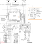
I have a 10minute timer in an old piece of audio equipment I would really like to get rid of. Inside the device, theres a micro controller CXP5058 that consists of 8bit timers. In this case an external oscillator is present, which I think is referred to for timing reference, I have no idea about this sort of thing only what I've wrote and some experience with a solder iron.


So in light of that what would be the easiest way extend or disable the timer?
 

your problem is not clear.

If you do not have micro-controller reprogramming facility,
you can't change anything in it.

- - - Updated - - -

you can use 555 timer IC for timing purpose but your problem is not clear.
explain it further.
 
  • Like
Reactions: Giro

    Giro

    Points: 2
    Helpful Answer Positive Rating
Hi,
Glad you asked.
No access to programming facility. This chip is needed intact for the device it is housed in to work. The whole controller forms part of a tape loading mechanism in a DAT Recorder.
I wonder if the timer inside the chip can be turned off or at least extended somehow without affecting the rest of the device.

What effect would the removal an External Oscillator or EXTAL from a micro controller have in general..?

I had hoped for someone to take a quick look at the datasheet I provided in Post 1, if that is possible, there isn't too many pages, barely any text. I'm under the impression micro-controllers are pretty much the same, as far as 8bit timers are concerned, I wouldn't have posted otherwise. :)

I have a solder iron and a MultiMeter if thats any use.


Thanks for your reply
I look forward to suggestions or more questions.
 

Its a mask programmed device so you can't alter any internal settings. It holds more than a timer, the other parts of the MCU will be working at the same time, doing other functions in the tape drive. You can slow the whole device down which will have the effect of making the timer run slower but everything else will reduce in speed as well, to do that, change the 4.19MHz crystal for one with a lower frequency but beware that it might stop other time critical operations working at all.

You also have to consider that the timer inside the device may not be directly controlling something on the outside, for example it could be working like a metronome sets a musical beat and the operation you want to slow down may be on every fiftieth beat with other things working on every tenth or eleventh beat. A whole sequence of events could depend on the one timer.

Being a mask programmed device, you can not change the code inside it anyway, somewhere there will be a copy of the software it runs and a special compiler to convert it to binary values. They are then loaded into the ROM memory at the factory. You would need to adapt the original program, convert it to a new binary file then request a production run of new devices. Given that most manufacturers will not consider orders for less then 5,000 devices I would guess that would be out of the question!

Brian.
 
Truly informative post, thanks Brian. Changing the crystal, I'll keep that in mind.

In any case, its definitely possible to make this thing go longer than 10m, I know this because there was an aftermarket version of this recorder unit, modified to do just that.

It seems 'easy enough' change things without re-programming...
For instance, one mod I undertook involved simply lifiting a diode and that enabled the unit to record at non-default sample rates! If I had the modified aftermarket unit with the extended timer modification I would inspect it but I don't... :???: I've scoured the web for information to no avail.

BTW It is actually possible to extend the timer under normal conditions manually via a REC button on the recorder however this is more of a reset more than anything, i.e. one would have to repeatedly press that REC button every 9m or so.

I noticed there are INT and RST pins on the MCU which may be related? I've attached the circuit the MCU is enclosed in. Anyone willing to have a look at that to see if RST or INT can be changed, feel free. Any more, even remote clues very much appreciated.


Ta, Giro
 

Attachments

  • Untitled.png
    Untitled.png
    237.7 KB · Views: 140

@Giro
I think you got the detailed answere from betwixt.
You can not change only the timer setting by changing the crystal.
you can trace out the effects after defined time (10 mins you mentioned earlier).
you can replace that by some other device like 555 timer by de-soldering the respective pin.
 

Unforunately, the 'Rec' button is part of a scanned matrix which makes it tricky to work with, however, now I can see the schematic there is a potential solution using the existing processor. What you need to do it mimic the 'Rec' button being pressed before the 10 minutes has elapsed. Before going into detail, the way it works is when the button press is detected it does something in software to 'top up' the timer for a further 10 minutes, it doesn't directly change any of the electronics, it just alerts the processor to take appropriate action.

The RST pin is the master reset input, it basically sets the IC back to a known state when the power turns on, it can't and shouldn't be used at any other time.
The INT pin is the interrupt input, its a hardware signal that diverts the program flow to a special routine then continues from where it was when that routine finishes. It isn't possible to see where it comes form on that section of the schematic but it is probably a sensor somewhere on the device. You can't re-purpose it anyway as the software it triggers will be specific to handling what ever caused it.

Back to the 'Rec' button, if you had an oscilloscope to see the signals it would be fairly easy to fake the switch closing at fixed intervals. Without knowing the signal polarities or timing, it would be safest to do it with a small relay and timer circuit. What you want to happen is the switch closes for maybe 0.5 second after say 9 minutes so it prolongs the timeout period. To do that you need two timers, one for the 9 minutes and other triggered by it to give the 0.5 seconds relay time. It can be done in just a few components and for little cost. How confident are you at opening up the device and performing some invasive surgery? I have no idea of the component layout so I can't say exactly where you need to attach wires but I can tell you where the points are on the schematic if you can trace them yourself.

Brian.
 

The MCU is reachable. Most of the traces pass via diodes just before they break off to another PCB. I don't have the tool to solder at the IC terminals which is surface mounted but the diodes provide a tap point. Its actually D712 that is lifted for that sample rate modification I mentioned.
I can tell you where the points are on the schematic if you can trace them yourself.

Brian.

I'm all ears/eyes...

I'm guessing two 555s for starters, right? I have an account with cpc/farnell...
 

Two 555s or one 556 (which is a dual 555). You might find Farnell or CPC, which are essentially the company anyway, are expensive when you add postage. If you have a Maplin store near you you might save some costs.

You will notice the schematic shows the buttons in a matrix or rows and columns, the way it works is one of the 'T' lines is set to 5V and the others are set to 0V, then the 'I' lines are read in. If all the 'I' lines are at 0V it means none of the switches between them were pressed. If one of the 'I' lines goes to 5V the micro can tell which switch was closed because it can work out which it was from the intersection of the 'T' and 'I' signals. That 'T' then goes to 0V and the next one goes to 5V and the process repeats untill all the switches have been scanned.

That makes it a bit difficult to electronically fake the button being pressed because to be identified as only the 'Rec' button, the signal must be present only during the time that 'T' line was driven high. It would be easier to use a real switch wired across the button to do it and thats where the relay comes into play. A relay is just a mechanical switch operated by an electromagnet. The magnetism can be turned on and off by the 555/556 timer. The advantage of doing it that way is the relay contacts are electrically isolated from the timer circuit by the mechanism so there is no chance of the timer influencing the key matrix or vice versa. The relay contacts would be wired across pin 1 of CN973 and pin 8 of CN977 on the button circuit board so there is no need to do micro-surgery on the IC itself.

Brian.
 

So a timer triggers a relay every 9m which shorts pins 1 and 8 (corresponds to REC push) and another timer demagnetizes relay after 0.5s.

A relay prevents the 555 contaminating the MCU which otherwise needs 2 timers.

Is it not possible to have one timer alone to do the short?

I searched for perhaps all in one timer+relay theres no such thing in IC form. All I see are circuits based on 555. either that or its one of these somewhere:
AH3.jpg
Haha.
 

Thats almost correct - apart from the picture :-?

In practice you would use one timer in astable mode (continuously oscillating) with a period of 9 seconds and it's output would trigger the second timer in monostable mode (one pulse then waits for triggering again). The second timer drives the relay to fake the switch being closed.

You won't find a combined relay and timer but you can use a small mechanical relay like this:
**broken link removed**

It can be driven directly from the output of a 555/556 timer.

Theoretically, you could use one astable timer with an extreme on/off ratio so it was off for 9 minutes then on for 0.5 seconds but thats a ratio of more than 1000:1 which would be difficult to build without precision components. There are other methods of generating regular short pulses but the two timer method is simplest unless you are familiar with electronic circuits or want to try programming a simple microcontroller.

Brian.
 

Yeah the picture I was being funny,

I'll have a glance at the 555/6 datasheet and post here if I get stuck anywhere.
Theres a Maplin local,

Thanks again!

Giro
 

Status
Not open for further replies.

Similar threads

Part and Inventory Search

Welcome to EDABoard.com

Sponsor

Back
Top