Continue to Site

Welcome to EDAboard.com

Welcome to our site! EDAboard.com is an international Electronics Discussion Forum focused on EDA software, circuits, schematics, books, theory, papers, asic, pld, 8051, DSP, Network, RF, Analog Design, PCB, Service Manuals... and a whole lot more! To participate you need to register. Registration is free. Click here to register now.

[Moved]: ESD protection with PESD implant

Status
Not open for further replies.

sy

Newbie
Joined
Nov 9, 2007
Messages
5
Helped
0
Reputation
0
Reaction score
0
Trophy points
1,281
Activity points
1,353
Dear Friends:

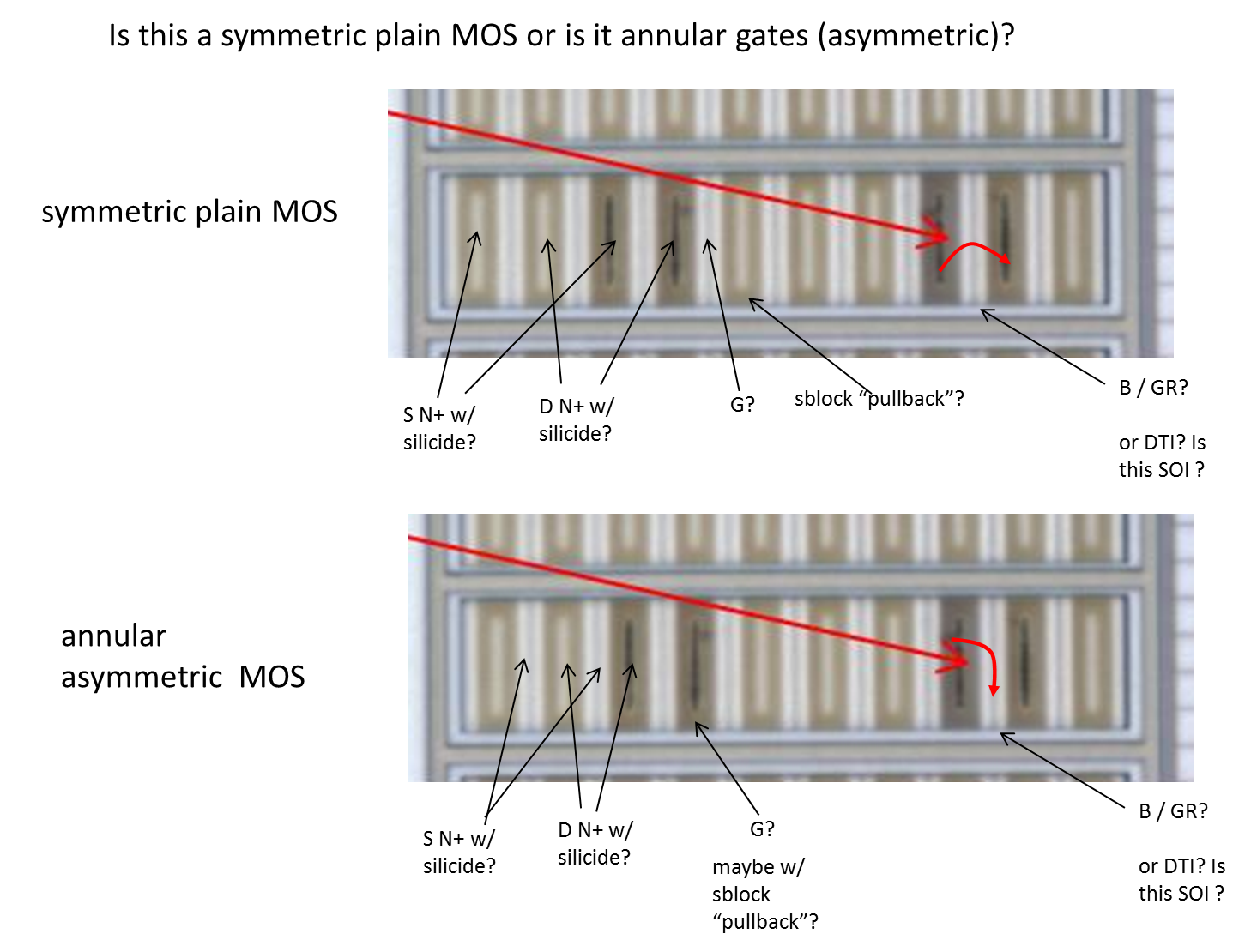
I use simple diode+RC-INV-bigFET to protect ESD for my IC. Diode+RC-INV-bigFET are from foundry standard IOS. Bad news is it cannot pass MM 200V test. Damage occurred at the first device in circuits, which is a switch, as below image shown , even though I do follow ESD rules. Seems my internal circuits are more susceptible to ESD stress.

Because I cannot revise the full chip, and the failure is marginal, i.e., can pass MM150V, but cannot pass MM200V, does it make sense to add PESD implant on the drain side of the switch to improve ESD by simply revising one mask layer?

Thank you all for your advice in advance!!

esd.png
 

Re: ESD protection with PESD implant

What does this "PESD" implant do to any given
device? Looks to be foundry specific jargon to me.

What is your failure mode? Overcurrent or overvoltage?
This goes directly to your device design.

Any device attached to a pad should follow ESD rules.
The drawing you show, shows it direct connected.
Therefore it is -not- "internal". It should have guardrings,
salicide block and pullbacks, all the features of any other
"blessed" I/O device.

"diodes and clamp" protection works for slow, current
limited human body model because clamp actuation
delay just doesn't matter. Machine model you only get
a tiny bit of help from the model inductor (and whether
this bears any resemblance to your tester handler on
a bad day, is an entirely other question) and you need
a really fast clamp trigger, really low clamp path loop
resistance and a "victim" device that can take a punch
as long as the clamp requires to do its job (if it even
can, against a 200V source model with not much
limiting of long-pulse current).

So back to just what "PESD" can do for you, regarding
any of these issues, any or all of which can break a
FET....
 

Re: ESD protection with PESD implant

Dear dick_freebird:

Thank you very much for your explanation.

Here I reply your questions as follows:
1. PESD means P-type ESD implant, it's implant beneath drain side of NMOS. It's used to reduce breakdown voltage and snapback voltage of NMOS. I attach below image for your quick reference.
2. My case is overvoltage failure. It cannot pass machine mode 200V.
3. NMOS switch does connect to pad directly, it also followed ESD rules, like you mentioned, including guard rings, salicide block...

I know "diodes and clamp" protection may not work effeciently for machine mode ESD, but for now I can only try to robust the victim device- NMOS switch. Based on your experience, do you think if the robustness of the victim device can be some improved by adding P-type ESD implant?

Thanks again for your advice!!

PESD.png IV curve.png
Source of above images: http://www.ics.ee.nctu.edu.tw/~mdke...tion in 0.18-um salidided CMOS technology.pdf
 

Re: ESD protection with PESD implant

OK. So PESD makes a poor-boy zener (or punchthrough)
which will dump current to the substrate (or PWell - and
if PWell, inside a NWell, you need to look at the exit path).
So far, so good.

But you are dealing with a threat model capable of 3A or
more, so what either of these do at 15mA (left) or 90mA
(right) is almost a don't-care (even if they were for your
actual technology). The no-PESD trace does not see
enough current to deduce its ohmic resistance and the
region shown may be channel punchthrough.

Failure mode can be voltage mode (gate rupture) or
current mode (interconnect fusing) or power density
(junction spiking). Yes, you fail at some voltage. That
doesn't make the failure voltage mode. Looking at some
SEM micrographs at the threshold of failure would be
informative. Looks to me like either of the I-Vs would
let a 3A pulse develop enough load-line voltage to
rupture a 3.3V gate oxide (I'm used to seeing 10-11V
for 3.3V technologies, more aggressive foundries
might be worse, no idea what your flow can take for
short pulse oxide stress).

If the switch FET is inside a 2-stage clamp and still
it blows out while the pad protection devices do not,
that's a head-scratcher. But is that really happening?
Or is it just high leakage on a switch pin and no idea
of the specific fail-site?

If you have some SEM photos of the failure site it
might help to focus.
 

Re: ESD protection with PESD implant

Thank you so much dick_freebird!!

I think I understand your explanation. I have just got the photo of damaged spots(I delayered the metal layers and observed in microscope). Damage at 3.3V switch is confirmed. The exact location is at drain side of the big 3.3V switch and the damage is localized. As you explained, could be channel punch or maybe junction breakdown induced localized high power density, causing the burn-out.

Therefore, as you explained, P-type ESD under the drain side of the 3.3V switch could be a choice to mitigate without greatly changing the design, am I correct? Or do you have other better suggestions?

Thanks a again!!
Damage.jpg
 

Re: ESD protection with PESD implant

To me, the black marks in the switch device look
like the contacts have been roasted (more current
mode to my thinking). There also looks to be a lot
of either damage or trash at a couple of points in
the pad cell (perhaps the primary stop-diodes)?

PESD under the stop-diodes, only helps if the diodes
are breaking down as the protection mode. They
should be operating forward to clamp, forward from
clamp, to complete the current loop. Same for the
switch, letting the drain break down earlier may only
reduce local power by some tens of percent (say, your
at-current breakdown voltage drops from 10V to 8V,
current roughly unchanged, you drop local self heating
by 20%). What PESD does do, is hold voltage below
gate ox rupture level. But my take on the photo says
you haven't put any current through the gate, only
D (and S, if the "major stripes" are SGDGSGD...DGS as
I make it out).

Question about device construction details. Looks to
me (fuzzy as it is) the devices could be "straight" (the
thin full width beige stripes would be the gates, the fat
brown regions sblock, the tan inside them alternating
S and D) or they could be annular style (full width beige
are S, fat brown is G (maybe inside sblock) and inner tan
would be D).

If the white ring is P+ guardring and the style is annular
then the mode is probably D-B breakdown and PESD could
at least improve the damage threshold.

If the white ring is DTI and this is a RF SOI technology
(who else makes pin-pin CMOS switches these days,
and what's the preferred platform?) then I don't see
a robust body contact (FDSOI, you tend to use none
because the thin body can only be contacted via a
T-gate / H-gate structure and fails you when you really
need it).

If symmetric MOS then the current path for the damaged
fingers is S-D and the contacts are burning. Why no damage
between them? The sparse failures (if current mode)
indicate that silicide block extent is too short to enforce
good current sharing at onset of breakdown (but more
would screw your on resistance, and fixing on resistance
would blow out cell size and up the Cgd, killing RF isolation).

Give some thought to the low level device structure,
this will say what the current path involves and likely
whether a voltage (gate rupture) or current / power
(burned contacts) mode. Maybe draw yourself a vertical
cross section about the adjacent failure sites assigning
the electrical connections and the likely current loop
through the device, and maybe even the predicted
ohmic voltage developed across features under (say)
3-5A, divided by N burn marks, imposed on a finger
(or finger pair - 2 of three sites seem pairwise). Contact
resistance drop, D-B breakdown, gate situated across
D and B tied to (???) and so on. And then see how this
changes if D-B breakdown drops from 10V to (say) 7V.
Current remains the same, distribution of heat may
change some - enough to help? Maybe if you passed
180V MM and failed at 200. Maybe not if you pass 151V
and fail 155V. Your ESD test steps are coarser (percent
wise) than the PESD impact to BVdb may be. There's a
bit of a knowledge gap there as well.

Experience says SOI RF switches are just going to be
lousy for pin-pin ESD - unless your gate drive network
just happens to make them all turn "on" dynamically
at fast risetimes, so that the channel conducts it all
across, at low resistance. This can work for a large
signal switch, say half an ohm for 50 ohm systems at
low insertion loss, and a (highly) resistive gate drive.
But a 5-ohm small signal switch, and 5A, vs a 10V BVox...
do the math. On both gate rupture, and the Joule
energy you deposit in the devices.

Which on SOI, has nowhere good to go but to pushing
silicon temperature toward Si-Al eutectic....


Re: ESD protection with PESD implant

Thank you so much for your explanation, dick_freebird!!

Sorry for my vague images and unclear comments, causing you have to make all kinds of assumptions. Here I re-attached image with clearer comments in it. Confirmed there is damage occurred at drain side of switch only, stains in pads are simply “trash” left during delayer process, not damage.

This is not for RF application, it’s simply consumer IC based on typical P-type Si wafer. The outer ring is PWELL guard ring with Boron implant.

I got your point that my ESD test steps are coarser, and I will try to look into the failure further from perspective of low level device structure as you suggested, trying to figure out how much extent I might can expect to improve by simply adding P-type ESD implant to reduce the breakdown voltage at the drain side of the switch.

Thanks again!!
Switch.jpg
 

Status
Not open for further replies.

Part and Inventory Search

Welcome to EDABoard.com

Sponsor

Back
Top