electronika.design
Junior Member level 1
Hi everyone,
I am trying to complete a circuit of mine, where I need a Latching circuit to keep my output latched once an some signal occurs at the input... And i can reset the system by resetting the supply of the circuit which is 24VDC.
I did some research and using some resources designed one for my purpose..
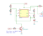
I did so using 2 transistors --- 1 NPN and 1 PNP
I am using an optocoupler TLP181 at the input just to keep isolation...
I tried doing this on Breadboard... it works almost all the times, though there are sometimes I come across some problems like
1) It automatically latches before providing input(problem solved)
2) It doesnt latch even after providing the correct input.
I need a solution for my second problem where it does not latch even after input being provided..
After providing signal to the base of the NPN, NPN turns on but it shud also turn on the PNP which it doesnot...
Please take a look at the circuit and do let me know where i am going wrong...
Thanks already!
(P.S.- not planning to use an SCR)
I am trying to complete a circuit of mine, where I need a Latching circuit to keep my output latched once an some signal occurs at the input... And i can reset the system by resetting the supply of the circuit which is 24VDC.
I did some research and using some resources designed one for my purpose..
I did so using 2 transistors --- 1 NPN and 1 PNP
I am using an optocoupler TLP181 at the input just to keep isolation...
I tried doing this on Breadboard... it works almost all the times, though there are sometimes I come across some problems like
1) It automatically latches before providing input(problem solved)
2) It doesnt latch even after providing the correct input.
I need a solution for my second problem where it does not latch even after input being provided..
After providing signal to the base of the NPN, NPN turns on but it shud also turn on the PNP which it doesnot...
Please take a look at the circuit and do let me know where i am going wrong...
Thanks already!

(P.S.- not planning to use an SCR)

