Continue to Site

Welcome to EDAboard.com

Welcome to our site! EDAboard.com is an international Electronics Discussion Forum focused on EDA software, circuits, schematics, books, theory, papers, asic, pld, 8051, DSP, Network, RF, Analog Design, PCB, Service Manuals... and a whole lot more! To participate you need to register. Registration is free. Click here to register now.

[SOLVED] Different Results in Transient Simulation with S-parameters from file in ADS

Status
Not open for further replies.

votientu

Member level 2
Joined
Oct 27, 2012
Messages
47
Helped
0
Reputation
0
Reaction score
0
Trophy points
1,286
Activity points
1,647
Hello,

I have a simulation in the ADS Transient where I have a 3 ports imported S-parameters.

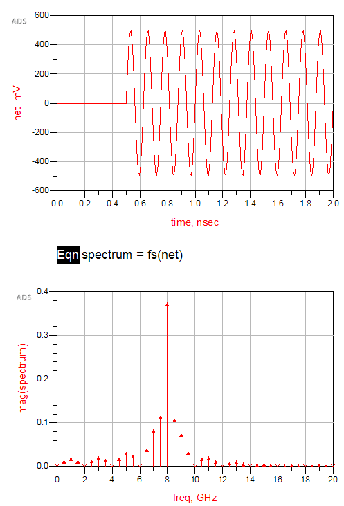
The time domain source is the sin wave at 8 GHz and at this frequency the S21 and S31 are at the same level (only the phase shift of 180 degree).

But the voltages at two outputs ports are not at the same level. Could you explain me why ?

I did the test where I replace the 3 ports S-parameters by the ideal power divider, the outputs are at the same level.
I also verified the 3 ports imported S-parameters with the S-parameter simulation in ADS and the outputs are at the same level at 8 GHz.

I have also the warning "Highest frequency in data is 1e+10 Hz, which is smaller than the maximum source bandwidth 4.8e+10 Hz." meanwhile my voltage source is only at 8 GHz.

Thanks for your help !

View attachment TDK.tar.gz

Ecran8.jpg
 
Last edited:

Ecran9.jpgI tested it at 8 GHz and 6 GHz as well. I forgot to change it to 8 GHz but it has the same problem.
 
Last edited:

I have also the warning "Highest frequency in data is 1e+10 Hz, which is smaller than the maximum source bandwidth 4.8e+10 Hz." meanwhile my voltage source is only at 8 GHz.

Can you plot the spectrum of your transient waveform, for this 2ns analysis period? Have you tried with EM simulation down to DC?
 

- - - Updated - - -

Can you plot the spectrum of your transient waveform, for this 2ns analysis period? Have you tried with EM simulation down to DC?
It is the ideal sin waveform. When I replace the imported 3-ports S-parameter by the ideal balun, it has the same message but the two outputs are equal in amplitude.
So I think that the problem is only at the imported 3-ports S-parameter, but I don't know how to explain because at 8 GHz the imported S-parameter shows the equality at the two outputs ports.
Of course, the imported 3-ports S-parameter does not have the same input impedance at ports 2 and 3 (16.7 Ohm) as the ideal balun (100 Ohm). But as the input signal is at port 1, I don't see any effect of the input impedance at ports 2 and 3.
 

It is the ideal sin waveform.

I disagree. In the transient plot that you show, there is a 0.5nS period where voltage is zero, and then we have sinewave for only 1.5ns.

But hey, it's your model, so feel free to ignore my advice. Good luck anyway!

Volker ,
Keysight Certified Expert EDA

- - - Updated - - -

 
I disagree. In the transient plot that you show, there is a 0.5nS period where voltage is zero, and then we have sinewave for only 1.5ns.

But hey, it's your model, so feel free to ignore my advice. Good luck anyway!

Volker ,
Keysight Certified Expert EDA

- - - Updated - - -

I misunderstood you. It is as you said, the sin wave in the limited period, so the spectrum extended to 6.4e10 Hz.
It explains the warning.

However, it does not explain the different outputs.
With the three ports, if |S21| = |S31|, I do not see why the output at port 2 |out2| is different to the output at port 3 |out3|.
The imported S-parameters from S-parameter Simulation is in the same impedance matching as the Transient Simulation.

- - - Updated - - -

Here the pure sin wave :
Ecran10.jpg
 

I have done the same simulation in AWR and the waveforms are same as expected.I think there are some tricks in convolution technique of ADS.
TDK.png
 
I have done the same simulation in AWR and the waveforms are same as expected.I think there are some tricks in convolution technique of ADS.
View attachment 137882

It is very interesting. Could you show me the simulation in AWR ?

Could you plot the sum of the two outputs in the small scale ?

Thanks !
 

However, it does not explain the different outputs.
With the three ports, if |S21| = |S31|, I do not see why the output at port 2 |out2| is different to the output at port 3 |out3|.

Only for the center frequency in this spectrum, you have |S21| = |S31|.

Your comparison, the ideal wideband divider, works because it is wideband and splits equally for all the spectrum components.
In your *.s3p file, there might be missing data for some of the frequency range where this pulse has relevant spectral components.

If you upload the ADS workspace in proper archive format (*.zip format not *.tar.gz), or at least your *.s3P file, I can have a closer look.
 
Last edited:

Ok, but I also need your data file "/home/tv247297/work/ADS/TDK/Rat_race.s3p"

In the meantime, I used "marchand_balun.s3p" from your ADS project, simulated in my own testbench, and that looks fine in transient simulation. ADS version is 2016.01

march.PNG

View attachment timedomain_spectrum_wrk.zip
 
Last edited:

It works with Marchand Balun but not with Rat Race Balun, even they have the same S parameters at 8 GHz. That why I dont understand.

The rat_race.s3p is also in my project with the marchand_balun.s3p
 

I see ....

Everything looks fine in AC analysis. The problem is in transient analysis only, and the difference between outputs changes if we change the S3P interpolation settings. I keep thinking that we don't have sufficient wideband data to do transient analysis for this coupler, which has a much sharper frequency response than the marchand data.

Edit: There is a bunch of undocumented convolution settings in the S3P element. Maybe you should get in touch with ADS support.
 
Last edited:

It works with Marchand Balun but not with Rat Race Balun, even they have the same S parameters at 8 GHz. That why I dont understand.

The rat_race.s3p is also in my project with the marchand_balun.s3p
I suggest you to re-simulate your Rat-Race Balun with finer simulation steps-for instance using with adaptive steps in Momentum over a bit larger frequency band.
 

I asked ADS about this problem, and finally it comes from effectively the interpolation in ADS.
It needs to extend the S-parameter from 0 Hz to 8 GHz or more, so that the time simulation can work correctly.
 

Status
Not open for further replies.

Part and Inventory Search

Welcome to EDABoard.com

Sponsor

Back
Top