mertkan65
Junior Member level 3
- Joined
- Nov 24, 2004
- Messages
- 30
- Helped
- 0
- Reputation
- 0
- Reaction score
- 0
- Trophy points
- 1,286
- Location
- Ankara/Turkey
- Activity points
- 279
Please dont feed any AC to the input. Just short the input to a proper DC value and measure the output by the spectrum analyzer. If you can see a spectrum at 140kHz without any AC input, then your chip is oscillating at this frequency. Normally when the chip oscillates, you can always observe harmonics rather than sub-harmonics.
I could not find any spectrum analyzer to test. But when frequency changes (100kHz - 200Khz) all harmonics and sub harmonics are changing and the result is the same. I think it is not related directly with 140Khz, it is related with AC Input frequency, but how?
- - - Updated - - -
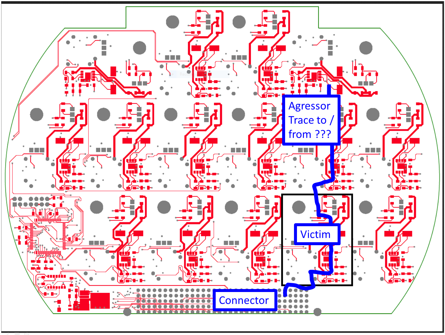
I wonder if the in- and output "detour" traces might cause problems due to parasitic coupling? They seem technically useless regarding the amplifier frequency range.
But I rather expect a problem a defect output transformer (e.g. with winding short). I presume, the transformer parameters can be verified in circuit with a suitable LCR meter. Or any other component defect.
We have tired different transformer and same transformer with different channels. Also tried to change primary inductance but no improvement. Other channles also have detour traces.
- - - Updated - - -
How many parts (PCBs) did you test?
3, but all are the same manufacturing party.
- - - Updated - - -
I would add a cap from pin 6 to pin 2 of the op amp. 10pf or so
We have tried that option, but no improvement.
- - - Updated - - -
What is coming in on that big connector, which the
problem channel "just happens" to be butted up
against? Do traces from the connector run below
the problem channel's more sensitive bits?
Sorry, but I could not understand exactly what you mean