Continue to Site

Welcome to EDAboard.com

Welcome to our site! EDAboard.com is an international Electronics Discussion Forum focused on EDA software, circuits, schematics, books, theory, papers, asic, pld, 8051, DSP, Network, RF, Analog Design, PCB, Service Manuals... and a whole lot more! To participate you need to register. Registration is free. Click here to register now.

Amplifier Layout Question

Status
Not open for further replies.

mertkan65

Junior Member level 3
Joined
Nov 24, 2004
Messages
30
Helped
0
Reputation
0
Reaction score
0
Trophy points
1,286
Location
Ankara/Turkey
Activity points
279
Dear All,

We have 15 channel class AB type amplifier on single PCB. All these channels generated with same schematic with top sheet and room layout. 14 Channel works fine with calculated gain but 1 channel has a low gain according to others. We have try many things but we could not identify problem. Except Input and output of the channels, all the remaining traces are the same, we have exluce traces and made it through directly input components and very short cable with output but nothing changed. Do you have any idea for the layout problem? Please find schematic and signal at requested gain (bad signal) as attached.
 

Attachments

  • Schematics.PNG
    Schematics.PNG
    62 KB · Views: 65
  • DS0001.PNG
    DS0001.PNG
    22.5 KB · Views: 55
  • DS0002.PNG
    DS0002.PNG
    30.8 KB · Views: 51

Hi,

we can´t verify your layout, because you don´t show it.

It seems your input signal is distorted somehow. It is no clean sine.

I wonder: you run the amplifier with 140kHz , but the R1/C37 cutoff frequency is at about 80kHz.
You will not see max. gain (max amplitude).

For stability reasons I´d rather connect C37 directely to OUT of the LTC6090...but maybe this increases output distortion...
On the other hand then you could reduce it´s value.

Klaus
 

I would first assume that there is a wrong value placed somewhere in the layout of the last amp. I am assuming that you have eliminated a bad transistor as the culprit. I am also assuming that the layout for the last amp has been properly checked and verified.
 
Last edited:

I have got similar waveform before and I found that something is oscillating. From your figure it seems that the output has been modulated, and you can use the DFT to extract the frequency information. In addition, if something other than VCO is oscillating, the DC condition may be apart from the normal condition.
 

Hi,

we can´t verify your layout, because you don´t show it.

It seems your input signal is distorted somehow. It is no clean sine.

I wonder: you run the amplifier with 140kHz , but the R1/C37 cutoff frequency is at about 80kHz.
You will not see max. gain (max amplitude).

For stability reasons I´d rather connect C37 directely to OUT of the LTC6090...but maybe this increases output distortion...
On the other hand then you could reduce it´s value.

Klaus

Hi Kluas,

Thank you for your comment. Yes we are workng with 140kHz, but before this C37 capacitor the output always oscillating. It is for phase shifting. We try different capacitor values it changes gain but we could never get signal without oscillating. Therefore it is just a value for us now. We have increased gain with transformer ratio.

Also we have tried connecting C37 at output of opamp but result is worse than now, also for the other channels.

- - - Updated - - -

I would first assume that there is a wrong value placed somewhere in the layout of the last amp. I am assuming that you have eliminated a bad transistor as the culprit. I am also assuming that the layout for the last amp has been properly checked and verified.

Hi SLK001,

Thank you for your comment. Layout for the last amp is verified and exactly same with other amps. We have checked all values and there is not any wrong value. We have assemblied a new pcb just only this channel but result is not changed.

- - - Updated - - -

I have got similar waveform before and I found that something is oscillating. From your figure it seems that the output has been modulated, and you can use the DFT to extract the frequency information. In addition, if something other than VCO is oscillating, the DC condition may be apart from the normal condition.

Hi NovelPanda,

Thank you for your comment. As you experienced, we also think that something oscillating but we could not found. Could you please give details for the steps that you done to found what is oscillating? We can use DFT to extract frequencies, then what should we do? Also we tried to change all DC condition parameters but no result.
 

Maybe some parasitics (R or C) caused by PCB traces, that are different for this channel, versus other channels?
 

Hi:

As oscillation does not require an AC input, just short the input to a DC value, and measure the output spectrum, if it really oscillates then you can see clearly the oscillation frequency of the opamp. As for DC condition, what I mean is that you give the same voltage bias to the opamp then check the current. If the chip is oscillating then the current may be different from that of the normal amplification condition.
 

Maybe some parasitics (R or C) caused by PCB traces, that are different for this channel, versus other channels?

The other channels inputs also have same trace characteristic, roughly all calculations are the same. Therefore I dont think the reason is parasitic.

- - - Updated - - -

Hi:

As oscillation does not require an AC input, just short the input to a DC value, and measure the output spectrum, if it really oscillates then you can see clearly the oscillation frequency of the opamp. As for DC condition, what I mean is that you give the same voltage bias to the opamp then check the current. If the chip is oscillating then the current may be different from that of the normal amplification condition.

OK, I will try it tomorrow and let you know the results. Thank you for your clear explanation.
 

I believe that your issues are parasitic and layout related. Until you post a layout, I don't believe that you can get the help that you need.
 

I believe that your issues are parasitic and layout related. Until you post a layout, I don't believe that you can get the help that you need.

Agreed. Parasitics or something like that caused by layout (difference between different channels).
Matching parasitics is not easy, and we need to see the layout for that.

OK, what kind file do you need to see layout of pcb? Altium files or capture, pdf?
 

Hi,

Most users are happy with PDF.

Klaus
 

Hi,

Most users are happy with PDF.

Klaus

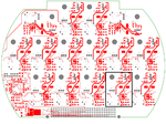
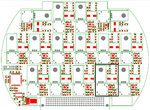
OK, please find attached.

- - - Updated - - -

Hi:

As oscillation does not require an AC input, just short the input to a DC value, and measure the output spectrum, if it really oscillates then you can see clearly the oscillation frequency of the opamp. As for DC condition, what I mean is that you give the same voltage bias to the opamp then check the current. If the chip is oscillating then the current may be different from that of the normal amplification condition.

We have tested your suggestion. At dc there is not any frequency at FFT, but for AC there are subharmonics of 140kHz, at 1/3 and 2/3. When frequency changes, harmonic frequencies also changes. For 180kHz there is only 1/2 subharmonic at 90kHz. Do you have any further suggestion?
 

Attachments

  • 0510-0009-0100-LD_D00.PDF
    13.3 MB · Views: 45
  • 0510-0009-0100-AD_D00.PDF
    4.3 MB · Views: 47

Hi,

Which of those amplifiers is the problematic one?

Klaus
 

Please dont feed any AC to the input. Just short the input to a proper DC value and measure the output by the spectrum analyzer. If you can see a spectrum at 140kHz without any AC input, then your chip is oscillating at this frequency. Normally when the chip oscillates, you can always observe harmonics rather than sub-harmonics.
 

I wonder if the in- and output "detour" traces might cause problems due to parasitic coupling? They seem technically useless regarding the amplifier frequency range.

But I rather expect a problem a defect output transformer (e.g. with winding short). I presume, the transformer parameters can be verified in circuit with a suitable LCR meter. Or any other component defect.
 

What is coming in on that big connector, which the
problem channel "just happens" to be butted up
against? Do traces from the connector run below
the problem channel's more sensitive bits?
 

I would add a cap from pin 6 to pin 2 of the op amp. 10pf or so
 

Status
Not open for further replies.

Part and Inventory Search

Welcome to EDABoard.com

Sponsor

Back
Top