Continue to Site

Welcome to EDAboard.com

Welcome to our site! EDAboard.com is an international Electronics Discussion Forum focused on EDA software, circuits, schematics, books, theory, papers, asic, pld, 8051, DSP, Network, RF, Analog Design, PCB, Service Manuals... and a whole lot more! To participate you need to register. Registration is free. Click here to register now.

long distance cell phone detector

Status
Not open for further replies.
Thats a method of finding average voltage values in different ways, it has nothing to do with your cell phone detector.

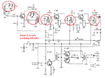
All the schematics so far are either wrong and wont work at all (post #17) or are nothing more than wide spectrum electrostatic/electromagnetic detectors. To do the job correctly you need to follow the advice already given. It involves RF circuitry, not op-amps. If I place my cell phone on top of my stereo amplifier, it makes a noise but that doesn't make the stereo a phone detector.

Brian.
 
Why don't you understand that a cell phone is a radio transmitter that uses narrow bands of radio frequencies. To detect a cell phone transmission you need a very complicated radio circuit tuned to the band you want but rejecting all the other kinds of radio, TV and communications frequencies. The circuits you showed are simply diodes that are NOT a complicated tuned radio circuit. They will pickup only very strong signals from radio and TV stations and taxi cab radios ALL AT THE SAME TIME.
 

All said you must use RF filters for your circuit but I want to make wide band about 1mhz-10ghz meter, why I must use a filter?!!!
Also I didn't said I want to make a cellphone detector.
 

Your thread is called "long distance cell phone detector".
 

To recall your initial post, you wrote
after building it many time it doesn't work correctly.
Sounds like you are trying to build the said cell phone detector, isn't it?

I want to make wide band about 1mhz-10ghz meter

Not completely impossible, but very difficult to achieve an uniform sensitivity over the wide frequency range. Consider that a piece of "antenna" wire acts as a capacitive pick up in the MHz frequency range, needing MOhm termination turns into a tuned antenna in the 100 MHz range and finally becomes too long to make a useful GHz antenna.

Incase of doubt, the sensitivity of your detector will be inverse to implemented bandwidth.
 

To recall your initial post, you wrote
Sounds like you are trying to build the said cell phone detector, isn't it?


Not completely impossible, but very difficult to achieve an uniform sensitivity over the wide frequency range. Consider that a piece of "antenna" wire acts as a capacitive pick up in the MHz frequency range, needing MOhm termination turns into a tuned antenna in the 100 MHz range and finally becomes too long to make a useful GHz antenna.

Incase of doubt, the sensitivity of your detector will be inverse to implemented bandwidth.

I want to build as i said wide band meter not cellphone detector anymore, but I agree with you it's hard to do but its possible,
I found some of them
take a look at it.
View attachment portable_powermeter.pdf
 

The shown detector circuits have 50 ohm input, so they won't work well with an "electrically small" (e.g. < λ/4) antenna.
 

How can I amplify my wide band circuit, and which kind of amplifier I must use or I don't need to amplify it, I totally haven't any idea about that?I am confused now
 

Don't you live in a huge modern city with hundreds of radio, TV and communications transmitters? Or do you live in a huge old desert with only one transmitter?
Your idea about using a wideband detector will add all the signals and show their total level. An RF amplifier will probably be very overloaded by all the signals.
Why do you want to know the total level of all the signals that are around you??
No man I haven't any special reason to do that, Just for fun, what do you think If i put a tunable circuit first ?
 

I guess you do not know that a tuneable radio, TV or cell phone does not have just one simple tunable circuit which is an L and a C in parallel. Instead they have many tuneable circuits so that they receive only one of the hundreds of signals. Your idea of using only one tuneable LC will pickup maybe 20 or more signals at the same time.
Here is a simple cheap AM radio circuit. It has 5 tuned LC stages.
 

Attachments

  • AM radio.png
    AM radio.png
    130.1 KB · Views: 85
I guess you do not know that a tuneable radio, TV or cell phone does not have just one simple tunable circuit which is an L and a C in parallel. Instead they have many tuneable circuits so that they receive only one of the hundreds of signals. Your idea of using only one tuneable LC will pickup maybe 20 or more signals at the same time.
Here is a simple cheap AM radio circuit. It has 5 tuned LC stages.

I don't want to pickup 1 signal it required very complex circuit, but I heard about the variable LC..... I don't know only 1 LC can adjust to detect different frequencies
 

An LC can have its inductance or its capacitance adjusted for tuning. It is the most sensitive at its tuned frequency and less sensitive above and below its tuned frequency. A cheap radio has at least 5 LC circuits so that adjacent frequencies are attenuated so they do not interfere with the frequency the radio is tuned to.
 

An LC can have its inductance or its capacitance adjusted for tuning. It is the most sensitive at its tuned frequency and less sensitive above and below its tuned frequency. A cheap radio has at least 5 LC circuits so that adjacent frequencies are attenuated so they do not interfere with the frequency the radio is tuned to.
So it's useless to my circuit cuz I want to detect all frequencies!!! Or I must build more than 10000 tuned circuits.
 

If you want to detect the levels of many RF frequencies at the same time then you need a very complicated product called an "RF spectrum analyser".
 

Not in the same time I prefer, I want to find a simple way to do that without many circuits, I guess a variable band pass RC filter will works well but I don't know what will happen in higher frequencies.
 

An RC filter is too simple to do what you want. Two RC filters (a highpass and a lowpass) can be a very simple bandpass filter.
 

An RC filter is too simple to do what you want. Two RC filters (a highpass and a lowpass) can be a very simple bandpass filter.
No, I want to use variable capacitors and resistors.

- - - Updated - - -

I bought an AD8317 Amplifier without knowing size of it, its size is 3 mm I can't see it 8-O :bang:
 

One RC produces a very gradual attenuation when the frequency is changed. You can make a Multiple Feedback bandpass filter with an amplifier, some capacitors and some resistors. It has a narrow bandwidth at its peak.
An LC has resonance and can have a high Q so that at its peak the bandwidth is very narrow.
You should never buy an IC without looking at its datasheet.
Here is a MFBF:
 

Attachments

  • Multiple Feedback bandpass filter2.PNG
    Multiple Feedback bandpass filter2.PNG
    13 KB · Views: 91
Status
Not open for further replies.

Similar threads

Part and Inventory Search

Welcome to EDABoard.com

Sponsor

Back
Top