Continue to Site

Welcome to EDAboard.com

Welcome to our site! EDAboard.com is an international Electronics Discussion Forum focused on EDA software, circuits, schematics, books, theory, papers, asic, pld, 8051, DSP, Network, RF, Analog Design, PCB, Service Manuals... and a whole lot more! To participate you need to register. Registration is free. Click here to register now.

Navigation through a path in Vivado

Status
Not open for further replies.

msdarvishi

Full Member level 4
Joined
Jul 30, 2013
Messages
230
Helped
1
Reputation
2
Reaction score
1
Trophy points
18
Activity points
2,349
Dear all,

I am coming back to this issue to say the great part of problem issued in the post here got solve but, a new restriction exists that I do not know is it a restriction in Tcl scripting or it can be solved.

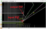
If you look at my attached snapshot, there are 2 PIPs highlighted with red circles that the first in bottom is an input PIP and the one at top is an output PIP. Using Tcl scripting, fortunately I could connect other parasitic wires to the input PIP at bottom as shown with white wires in the picture. You see, all the wires connected to this PIP are exiting this PIP.

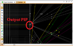
The problem is when I am trying to connect a parasitic wire to the PIP at top (please see the second attached snapshot) where the parasitic wires are entering that PIP since the PIP is an output. When I try to connect any of them to that PIP at top, I receive the following error which means the resource of that wires is unknown and it is correct since it does not recognize where that wire comes from !!


Code:
set_property route { { CLBLL_LL_AMUX  CLBLL_LOGIC_OUTS_L2  IMUX-L4 SE2END2  } } [get_nets  {Inst_StartPoint_DFF/Qs}]
Code:
[COLOR="#FF0000"]ERROR: [Designutils 20-941] Did not find node resource, CLBLL_LOGIC_OUTS_L2, downhill from node, CLBLL_L_X2Y51/CLBLL_LL_AMUX.
Downhill node choices include:  CLBLL_L_X2Y51/CLBLL_LOGIC_OUTS20 [/COLOR]
.
Can anyone help me how to solve this problem ?


Thanks and Regards,
 

Attachments

  • Untitled3.png
    Untitled3.png
    29.9 KB · Views: 48
  • Untitled4.png
    Untitled4.png
    31.9 KB · Views: 50

Without the design database it will be very hard to figure out what is wrong. None of those white connections seems to be showing in the second picture, so is that input PIP even connectable to the Output PIP you show in the second picture?

My guess would be that the set_property_route command may have something wrong with the list of nodes. Possibly using the output PIP is not what you want to do, but I can't check this as I don't have an equivalent design.


Dear @ads-ee,

Thanks for your reply. Infact, concerning your question, the input PIP is connectable to the output PIP in order to configure the routing path. Meanwhile, I am trying to connect some parasitic wires to the input and output PIPs as well.

Also, concerning your point that you've said : "None of those white connections seems to be showing in the second picture", YES it is correct and normal because in the second picture I did click on the output PIP and so only its corresponding wires with input direction are shown while in the first figure, I did click on the input PIP and all the while wires correspond to the input PIP with the exit drection.

The problem that is stated here is that the script using the set_property route command does not accept any wire to be connected to the output PIP and returns the error mentioned in my initial post ! It is quite weird !
 

The problem that is stated here is that the script using the set_property route command does not accept any wire to be connected to the output PIP and returns the error mentioned in my initial post ! It is quite weird !

I don't believe you can specify output nodes you can only specify destination input nodes (loads). Try using the destination of that output PIP.

I might be wrong, but I think the command also has a route through option of some sort that perhaps the output PIP could be included in...along with the destination node.

Dear @ads-ee,

I completely agree with you ! Lots of trials we me were failed and I think no more trial is required since it has a logic reason : A destination output cannot be specified with an unknown source wire !!

Meanwhile, I will keep this post open and I will try to find a reasonable solution or another path for my trials and I will get back to come up with the new findings.

Sincerely,
 

Status
Not open for further replies.

Part and Inventory Search

Welcome to EDABoard.com

Sponsor

Back
Top