Continue to Site

Welcome to EDAboard.com

Welcome to our site! EDAboard.com is an international Electronics Discussion Forum focused on EDA software, circuits, schematics, books, theory, papers, asic, pld, 8051, DSP, Network, RF, Analog Design, PCB, Service Manuals... and a whole lot more! To participate you need to register. Registration is free. Click here to register now.

[PIC] Three Phase Fully Controlled Rectifier Design Related

Status
Not open for further replies.
I am posting my new question in this thread as it is related to Three Phase Controlled Rectifiers. My new project is Three Phase Fully Controlled Rectifier. Please see attached Circuit and tell me if it is correct especially the Anodes to MOC3021 connections.
 

Attachments

  • 3PFCR - Monochrome.PDF
    52.3 KB · Views: 87

Halfway wrong. Each MOC has to be connected between anode and gate of the controlled SCR.
 
  • Like
Reactions: Okada

    Okada

    Points: 2
    Helpful Answer Positive Rating
@FvM

Ok. FvM. I am sure the lower half SCRs anodes to MOC3021 connections were wrong. I have fixed them. See new circuit attached. Is it correct now ?

- - - Updated - - -

@FvM

Are the Anodes to MOC3021 connections correct in Attached Circuit (revision C) ?

I checked the 3 Phase signals and when R and B are positive Y will be negative. I analyzed to forward bias the required SCRs and made these new connections. If I am wrong then how to analyze the connections. Each SCR pair has to get forward biased during firing them.

Why the text books and online materials doesn't show an example circuit for connecting MOC3021 to Three Phase Controlled Rectifiers ?


Edit 2:

Ok FvM. Discard my previous circuits. I have fixed the MOC3021 to SCR anodes connections. Just check Revision D file and tell me if it is correct. I am sure it is correct but need a confirmation before building it on hardware. I considered the circuit as three separate Single Phase bridge rectifiers and super imposed them and made this circuit.
 

Attachments

  • 3PFCR - Revision B - Monochrome.PDF
    52.3 KB · Views: 84
  • 3PFCR - Revision C - Monochrome.PDF
    52.3 KB · Views: 77
  • 3PFCR - Revision D - Monochrome.PDF
    52.6 KB · Views: 77
Last edited:

What should be the gate triggering pulse width for Revision D Circuit posted in post #23 ? Revision D circuit is the correct one. It is just three controlled bridge rectifiers superimposed for 0, 120 degree and 240 degree phase angles.
 

Although Revision D looks right at first sight, it has still SCR gate terminals mixed up.
 

@FvM

Can you explain more. Can you provide a sample circuit for the SCRs anode to MOC30xx connection or tell me where I am doing wrong ?


Edit:

Wait, Sorry, I posted the wrong file. Revision D file is wrong file. I will post the correct file. By mistake I posted the wrong file.
 
Last edited:

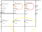
Anode 1 is with Gate 1...that is fine.
But then, you have Anode 2 with Gate 3, and then Anode 3 with Gate 5....that is only on the top SCRs, the bottom ones have similar issues.
 

Just read your schematic thoroughly

confusion.png
 
  • Like
Reactions: Okada

    Okada

    Points: 2
    Helpful Answer Positive Rating
I am really sorry. The Revision D file which I posted was the wrong file. It was a mistake in posting. Here is the correct file. Is this correct now ? The circuit attached in this post is actually the correct Revision D file and to avoid confusions I have renamed it Revision E file.
 

Attachments

  • 3PFCR - Revision E.PDF
    52.5 KB · Views: 84

For many years, I designed three-phase high power circuits.

When a mistake is made (even a trivial one), the circuit literally blows up and almost everything in it is destroyed. People could be hurt. The driven motor could be damaged. Seldom there are second chances with power electronics, like on a logic circuit.

I would strongly suggest, that you name consistently every single component in the signal path. That includes the variable labels in software, ports, the analog channels, boards and of course the drivers and the power SCRs.

You could use any label you want, but I would use the standard three-phase nomenclature used in the country where you live, i.e: R,S,T or U,V,W or L1,L2,L3 or R,Y B.
 
  • Like
Reactions: Okada

    Okada

    Points: 2
    Helpful Answer Positive Rating
@schmitt trigger

Ok. I will use Three Phase nomenclature for all required things in the project. I will first test all low voltage signals and if they are fine then only I will connect SCRs or power devices and only provide 12V or 24V AC input to SCRs and TRIACs for testing. If they work fine then only HV is used to test. I don't have much experience with power electronics. I have only experience with micrcontrollers. I have never worked with HV circuits.

- - - Updated - - -

Now what about the width of the gate triggering pulses ? Should I use 6x 60 degree pulses or 6x 30 degree pulses ?
 

This post is related to Three Phase Bridge Rectifier but it is not related to Controlled Rectifier. I was just checking how to make Three Phase Bridge Rectifier because I need this simulation circuit for making Controlled Three Phase Bridge Rectifier. Mods please don't move this post to Analog Electronics Section.

In the attached Proteus Simulation, Proteus Circuit (PDF) and Proteus Simulation Video I have shown how to connect 1 Phase and 3 Phase Voltage sources to respective 1 Phase and 3 Phase Bridge Rectifiers for simulation purpose. If only one voltage source is used then the input shows only half wave and output will be link half wave rectifier.

Using this simulation circuit scheme I will continue with this thread by posting controlled Three Phase Bridge Rectifier.

Please mods don't move this post to any other section because if somebody wants to make a controlled or normal three phase bridge rectifier simulation then this post will be useful.


Edit:

In the 1 Phase Bridge Rectifier Circuit there is 10ms delay between V2 and V3 AC voltage sources but in 3 Phase Voltage sources there is no delay that is they both start at the same time.
 

Attachments

  • Bridge Rectifiers.rar
    598.5 KB · Views: 85
Last edited:

Status
Not open for further replies.

Similar threads

Part and Inventory Search

Welcome to EDABoard.com

Sponsor

Back
Top