Continue to Site

Welcome to EDAboard.com

Welcome to our site! EDAboard.com is an international Electronics Discussion Forum focused on EDA software, circuits, schematics, books, theory, papers, asic, pld, 8051, DSP, Network, RF, Analog Design, PCB, Service Manuals... and a whole lot more! To participate you need to register. Registration is free. Click here to register now.

[PIC] Three Phase Fully Controlled Rectifier Design Related

Status
Not open for further replies.

Okada

Banned
Joined
Jun 16, 2016
Messages
1,159
Helped
129
Reputation
252
Reaction score
129
Trophy points
63
Activity points
0
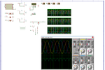
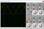
My question is Three Phase Fully Controlled Rectifier Design related.

I am doing only the simulation in Proteus. I am using three phase AC voltage source. I want to know,

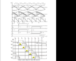
1. Is it good to use one ZCD circuit for say Phase R and then fire the first SCR pair at alphs (firing angle) and then fire the successive SCR pairs with a 60 degree (50 Hz AC, 3.33ms) difference or 3.33ms difference from the previous trigger time. I can detect ZC using INT pin and then disable it and then run a timer interrupt of (alpha delay) and then fire First SCR pair and then I run 3.33ms (60 degrees) timer interrupt and use a counter and increment it on each timer interrupt and firing successive SCR pairs and finally after all the SCR pairs are fired I will clear the counter and re-enable the INT pin ?

2. Use three ZCD circuits, one for each phase and fire the SCR pairs.

The 1st method doesn't allow me to detect phase failure but the second one allows.

I am referring this.

**broken link removed**
 

Attachments

  • Three Phase Fully Controlled Rectifier - Firing Angles.png
    Three Phase Fully Controlled Rectifier - Firing Angles.png
    3.9 KB · Views: 265
  • 5084599200_1352553566.png
    5084599200_1352553566.png
    63.4 KB · Views: 245
Last edited:

You could, but it is not a good design practice.

I would synchronize each phase individually with its own dedicated ZCD.

That way, a phase loss will not de-synchronize the remaining phases.

Decades of hard-earned experience with high-power electronics, dictate that redundancy is always your best friend.
 
  • Like
Reactions: Okada

    Okada

    Points: 2
    Helpful Answer Positive Rating
Ok schmitt trigger, I will go with 3 ZCDs.
 

[PIC] Problem With Three Phase - Controlled Half Wave Rectifier

My Problem is related to Three Phase - Controlled Half Wave Rectifier.

I am referring these

https://www.circuitstoday.com/polyphase-rectifiers

https://www.youtube.com/watch?v=mi26LHNmXj0

I am using PIC18F46K22 which has three INTx pins. I am using the three INTx pins for ZCD. On each INTx interrupt corresponding SCR is fired. The angle between each INT0 and INT1, INT1 and iNT2, INT2 and iNT0 interrupts is 120 degrees but once an SCR is triggered after alpha (firing angle) then it will conduct till the end of that half cycle. Only positive half cycles are rectified.

My AC frequency is 50Hz

When INTx occurs then I start a timer interrupt for required firing delay and after timer expires I fire the corresponding SCR but the B Phase ZCD circuit output signal is not correct and also I am not getting rectified DC at the output. I am getting a sine wave output. What is the problem ? I have attached my simulation circuit in PDF format and also the Proteus simulation.

- - - Updated - - -

Edit: Sorry mods.

I had opened more than 10 edaboard pages and by mistake posted this post (post 4) in this thread. It is related to a new thread I wanted to create named

Problem With Three Phase - Controlled Half Wave Rectifier

Please move post 4 of this thread to a new thread.


Edit 2:

Ok mods.

You have moved the thread

[PIC] Problem With Three Phase - Controlled Half Wave Rectifier

to this thread.

I got confused I had not seen that you have moved the new thread here.
 

Attachments

  • Three Phase - Controlled Half Wave Rectifier.rar
    346.4 KB · Views: 281
Last edited by a moderator:

Re: [PIC] Problem With Three Phase - Controlled Half Wave Rectifier

Edit:

The explanation of the working of Three Phase - Half Wave Rectifier in this video is wrong in the sense that it doesn't show the condition when two SCRs are On in the half wave rectifier.

https://www.youtube.com/watch?v=mi26LHNmXj0


If firing angle alpha is 0 then,

SCR1 will conduct from 0 to 180 degrees

SCR1 and SCR2 will both conduct from 120 degrees to 180 degrees

SCR2 will conduct from 120 to 240 degrees

SCR2 and SCR3 will both conduct from 180 degrees to 240 degrees

SCR3 will conduct from 240 to 360 degrees

SCR3 and SCR1 will both conduct from 240 degrees to 300 degrees

All Angles are w.r.t SCR1

Am I right ?

From the graph I see that magnitude (width) of ZCD R is not correct because magnitude of Phase R is not correct.
Also the ZCD B signal and Load signals are strange.

What is the problem ?

In the previous post I attached monochrome schematic and in that it is difficult to analyze graph data.
Here I am attaching color schematic. It will be easier to analyze the graph. Also schematic is changed. For ZCD circuits I used opto-couplers.

- - - Updated - - -

Edit:

mikroC PRO PIC project attached.


I see problem in ISR code.

I am considering three conditions for analyzing the ISR code and only considering SCR1 and SCR2 for analysis but it also applies for SCR2,SCR3 pair and SCR3,SCR1 pair

Condition 1

If firing angle is 0 degrees then at INT0 ZCD the Timer is started and it immediately without delay interrupts and fires the SCR1 and then there is 120 degree (6.67ms) for INT1 to occur. This condition has no problem with the code and also the 300us delay inside the ISR doesn't cause problem.

Condition 2

If firing angle is 120 degrees then INT0 occurs at 0 degrees and then timer runs for 6.67 (120 degrees) and then it interrupts to fire SCR1 but at the same time it is ZC for SCR2 and INT1 triggers and when INT1 triggers Timer is reset and restarted. So, what happenes here ? Timer ISR has 300us delay.

Condition 3

If firing angle is > 120 and <= 180 degrees then at 0 degree INT0 triggers for SCR as it is ZC for SCR1 circuit and a timer interrupt of more than 6.67ms (120 degrees) and <= 10ms (180 degrees) will be running but at 120 degrees that is 6.67ms INT1 (ZC for SCR2 Circuit) triggers and this resets and restarts the timer and so the SCR1 never triggers. Also same when INT2 triggers, timer is cleared and SCR1 never triggers and this repeats and so none of the SCRs fire. In INTx ISR there is a variable to select SCR for firing and it is scr_select_counter.


How to solve these problems ?


Code C - [expand]
1
2
3
4
5
6
7
8
9
10
11
12
13
14
15
16
17
18
19
20
21
22
23
24
25
26
27
28
29
30
31
32
33
34
35
36
37
38
39
40
41
42
43
44
45
46
47
48
49
50
51
52
53
54
55
56
57
58
59
60
61
62
63
64
65
66
67
68
69
70
71
72
73
74
75
76
77
78
79
80
81
82
83
84
85
86
87
88
89
90
91
92
93
94
95
96
97
98
99
100
101
102
103
104
105
106
107
108
109
110
111
112
113
114
115
116
117
118
119
120
121
122
123
124
125
126
127
128
129
130
131
132
133
134
135
136
137
138
139
140
141
142
143
144
145
146
147
148
149
150
151
152
153
154
155
156
157
158
159
160
161
162
163
164
165
166
167
168
169
170
171
172
173
174
175
176
177
178
179
180
181
182
183
184
185
186
187
188
189
190
191
192
193
194
195
196
197
198
199
200
201
202
203
204
205
206
207
208
209
210
211
212
213
214
215
216
217
218
219
220
221
222
223
224
225
226
227
228
229
230
231
232
233
234
235
236
237
238
239
240
241
242
243
244
245
246
247
248
249
250
251
252
253
254
255
256
257
258
259
260
261
262
263
264
265
266
267
268
269
270
271
272
273
274
275
276
277
278
279
280
281
282
283
284
285
286
287
288
289
290
291
292
293
294
/*
 * Project name:
     Three Phase - Controlled Half Wave Rectifier
 * Revision History:
     20170406:
       - initial release (A);
 * Description:
     Three Phase - Controlled Half Wave Rectifier Using SCRs
 * Test configuration:
     MCU:                    PIC18F46K22
                             **broken link removed**
     Dev.board:              Custom Board
     Oscillator:             XT, 4.0000 MHz Crystal
     Ext. Modules:           None.
     SW:                     mikroC PRO for PIC
                             [url]https://www.mikroe.com/mikroc/pic/[/url]
 * Author(s):                Okada
 * Project Start Date:       04/04/2017
 * Project Completion Date:
 * NOTES:
     - Three Phase - Controlled Half Wave Rectifier
 */
 
// LCD module connections
sbit LCD_RS at LATE0_bit;
sbit LCD_EN at LATD0_bit;
sbit LCD_D4 at LATC3_bit;
sbit LCD_D5 at LATC2_bit;
sbit LCD_D6 at LATC1_bit;
sbit LCD_D7 at LATC0_bit;
 
sbit LCD_RS_Direction at TRISE0_bit;
sbit LCD_EN_Direction at TRISD0_bit;
sbit LCD_D4_Direction at TRISC3_bit;
sbit LCD_D5_Direction at TRISC2_bit;
sbit LCD_D6_Direction at TRISC1_bit;
sbit LCD_D7_Direction at TRISC0_bit;
// End LCD module connections
 
sbit R_Phase_SCR_Gate_Trigger at LATD5_bit;
sbit Y_Phase_SCR_Gate_Trigger at LATD6_bit;
sbit B_Phase_SCR_Gate_Trigger at LATD7_bit;
 
#define PHASE_R 0
#define PHASE_Y 1
#define PHASE_B 2
 
const code char txt1[] = "F Angle: ";
const code char txt2[] = "C Angle: ";
 
const char character[] = {6,9,9,6,0,0,0,0};
 
char txt[32], i = 0;
unsigned char scr_select_counter = 0;
unsigned int timer_reload_value = 0x0000;
unsigned int raw_adc_value = 0, previous_raw_adc_value = 2048;
double scr_firing_delay_in_seconds = 0.0;
double previous_scr_firing_delay_in_seconds = 20.0;
double fosc = 4000000.0, timer_prescalar = 1.0;
double mains_frequency = 50.0;
double period = 0.0;
double duration_for_half_wave_of_ac = 0.0;
double duration_for_120_degrees = 0.006467;
double minimum_gate_trigger_delay = 0.0003;
double adc_factor = 0.0;
double timer_resolution = 65536.0;
double timer_tick_period = 0.0;
double scr_firing_angle = 0.0;
double scr_conduction_angle = 0.0;
 
//Timer1
//Prescaler 1:1; TMR1
void InitTimer1() {
    T1CON = 0x01;
    TMR1IF_bit = 0;
    TMR1H = timer_reload_value >> 8;
    TMR1L = timer_reload_value;
    TMR1IE_bit = 1;
}
 
void Interrupt() {
    if((INT0IE_bit) && (INT0IF_bit)) {
        INT0IF_bit = 0;
        //INT0IE_bit = 0;
        scr_select_counter = 0;
        InitTimer1();
    }
    else if((INT1IE_bit) && (INT1IF_bit)) {
        INT1IF_bit = 0;
        //INT1IE_bit = 0;
        scr_select_counter = 1;
        InitTimer1();
    }
    else if((INT2IE_bit) && (INT2IF_bit)) {
        INT2IF_bit = 0;
        //INT2IE_bit = 0;
        scr_select_counter = 2;
        InitTimer1();
    }
    
    if((TMR1IE_bit) && (TMR1IF_bit)) {
        TMR1IE_bit = 0;
        TMR1IF_bit = 0;
        //Enter your code here
        switch(scr_select_counter) {
           case PHASE_R:
                R_Phase_SCR_Gate_Trigger = 1;
                Delay_us(100);
                R_Phase_SCR_Gate_Trigger = 0;
                //INT1IE_bit = 1;
                break;
           case PHASE_Y:
                Y_Phase_SCR_Gate_Trigger = 1;
                Delay_us(100);
                Y_Phase_SCR_Gate_Trigger = 0;
                //INT2IE_bit = 1;
                break;
           case PHASE_B:
                B_Phase_SCR_Gate_Trigger = 1;
                Delay_us(100);
                B_Phase_SCR_Gate_Trigger = 0;
                //INT0IE_bit = 1;
                break;
        };
    }
}
 
void CustomChar(char pos_row, char pos_char) {
    char i;
 
    Lcd_Cmd(64);
 
    for(i = 0; i <= 7; i++)
        Lcd_Chr_CP(character[i]);
 
    Lcd_Chr(pos_row, pos_char, 0);
}
 
char *CopyConst2Ram(char * dest, const code char *src) {
    char *d;
 
    d = dest;
 
    for(;*dest++ = *src++;);
 
    return d;
}
 
void main() {
 
    CM1CON0 = 0x00;
    CM2CON0 = 0x00;
 
    SLRCON = 0x00;
 
    ADCON1 = 0x80;
    ADCON2 = 0b10110101;
 
    ANSELA = 0x01;
    ANSELB = 0x00;
    ANSELC = 0x00;
    ANSELD = 0x00;
    ANSELE = 0x00;
 
    TRISA = 0x01;
    TRISB = 0x07;
    TRISC = 0x00;
    TRISD = 0x00;
    TRISE = 0x00;
 
    PORTA = 0x00;
    PORTB = 0x00;
    PORTC = 0x00;
    PORTD = 0x00;
    PORTE = 0x00;
 
    LATA = 0x00;
    LATB = 0x00;
    LATC = 0x00;
    LATD = 0x00;
    LATE = 0x00;
 
    Delay_ms(200);
    
    LCD_Init();
    LCD_Cmd(_LCD_CURSOR_OFF);
    LCD_Cmd(_LCD_CLEAR);
 
    LCD_Out(1,1,CopyConst2Ram(txt, txt1));
    LCD_Out(2,1,CopyConst2Ram(txt, txt2));
 
    timer_tick_period = 1.0 / (fosc / 4.0 / timer_prescalar);
 
    //mains ac period
    period = 1.0 / mains_frequency;
    //duration for 180 degrees
    duration_for_half_wave_of_ac = period / 2.0;
    
    //**** duration_for_120_degrees = period / 3.0;
 
    //for raw adc value = 0 we have to get scr firing delay = 0 sec and
    //for raw adc value 1023 we have to get scr firing delay of 9.7ms
    //we don't take 10ms because there is a 200us delay after zero cross
    //and before the INT pin goes low and another 100us delay after INT pin
    //goes low and SCR fires for scr firing delay = 0
    //so, we subtract 300us from 10ms to get 0.0097 sec
    //if raw adc value is 1023 then we have to get scr firing delay of 0.0097
    //sec and so we have to use equation,
    //scr_firing_delay_in_seconds = raw_adc_value * 0.0097 / 1023.0
    //so, the factor for multiplying with raw adc value is 0.0097 /1023.0
    // which is (duration_for_half_wave_of_ac - minimum_gate_trigger_delay) / 1023.0
    //adc_factor = (duration_for_half_wave_of_ac - minimum_gate_trigger_delay) / 1023.0;
    
    ////adc_factor = (duration_for_120_degrees - minimum_gate_trigger_delay) / 1023.0;
    adc_factor = (duration_for_half_wave_of_ac - minimum_gate_trigger_delay) / 1023.0;
 
    INTEDG0_bit = 0;
    INT0IF_bit = 0;
    INT0IE_bit = 1;
 
    INTEDG1_bit = 0;
    INT1IF_bit = 0;
    INT1IE_bit = 1;
 
    INTEDG2_bit = 0;
    INT2IF_bit = 0;
    INT2IE_bit = 1;
 
    PEIE_bit = 1;
    GIE_bit = 1;
 
    while(1) {
 
          raw_adc_value = (unsigned int)ADC_Read(0);
          Delay_ms(1);
 
          if(previous_raw_adc_value != raw_adc_value) {
              //to get scr firing delay of 0 to 9.97ms (10ms - 300us, 180 degree) for 0 to
              //1023 raw adc //value
              
              //**** to get scr firing delay of 0 to 6.6467ms (6.67ms - 300us, 120 degrees)
              //1023 raw adc //value
              
              scr_firing_delay_in_seconds = (double)raw_adc_value * adc_factor;
 
              //only if adc value is greater than 0 then calculate the timer
              //reload value which is used in ISR to get the required scr
              //firing delay
              ////if(raw_adc_value > 0) {
              timer_reload_value = (unsigned int)(timer_resolution -
                                    (scr_firing_delay_in_seconds
                                     / timer_tick_period));
              ////}
              
              //as mentioned above there is 300us delay and for half of AC
              //period that is for 10ms, angle is 180 degrees, so for 300us
              //it is 5.4 degrees
              //so, to get scr firing angle between 5.4 degrees and (180 - 5.4)
              //degrees we use below equation
              //eg: if scr_firing_delay_in_seconds = 0 we get scr_firing_angle
              //= 5.4 degrees
              //if scr_firing_angle_in_seconds = 0.0097 then we get
              //scr_firing_angle = 174.6 degrees
              //due to initial 300us delay the scr can only conduct for max
              //174.6 degrees
              scr_firing_angle = 18000 * scr_firing_delay_in_seconds + 5.4;
 
              //finally scr conduction angle is calculated from below equation
              //eg: if scr firing angle is 5.4 degrees then scr conduction angle
              //is 180 - 5.4 = 174.6 degrees
              scr_conduction_angle = 180.0 - scr_firing_angle;
 
              //the scr firing angle floating point value is converted to
              //fixed length string with fixed lenght = 5
              FloatToStr_FixLen(scr_firing_angle, txt, 5);
              //the string is printed on LCD line 1
              LCD_Out(1,10,txt);
              //the degree symbol is printed on LCD at required position
              CustomChar(1,15);
 
              //the scr conduction angle floating point value is converted to
              //fixed length string with fixed lenght = 5
              FloatToStr_FixLen(scr_conduction_angle, txt, 5);
              //the string is printed on LCD line 2
              LCD_Out(2,10,txt);
              //the degree symbol is printed on LCD at required position
              CustomChar(2,15);
 
              //this is to make sure that this block of code is executed only
              //if adc value has changed
              previous_raw_adc_value = raw_adc_value;
          }
    }
}


Attachments

  • Three_Phase_Controlled_Half_Wave_Rectifier - Revision C.rar
    900.1 KB · Views: 136
  • Three Phase - Controlled Half Wave Rectifier - mikroC PRO PIC.rar
    69.3 KB · Views: 131
Last edited:

Re: [PIC] Problem With Three Phase - Controlled Half Wave Rectifier

I banged my head for 2 days and two days got wasted. Finally got some output but not sure if the output is correct. Have to analyze. Code is not changed. Problem was with simulation file. Two connections R phase connection and resistive load connection were both named R. Fixed the simulation file. Please check the attached Proteus simulation. I am not getting output for firing angle > 120 degrees (120 to 180 degrees). LCD is excluded in simulation. If needed enable it. See also attached Proteus simulation video.
 

Attachments

  • Three Phase - Controlled Half Wave Rectifier.rar
    718.2 KB · Views: 215

Re: [PIC] Problem With Three Phase - Controlled Half Wave Rectifier

I have modified the ISR code but still I am not getting output for firing angle >= 120 degrees and <= 180 degrees.

I have added one variable which is tested in INTx ISR code using if() conditions to fire the previous Phase SCR.


Code C - [expand]
1
2
3
4
5
6
7
8
9
10
11
12
13
14
15
16
17
18
19
20
21
22
23
24
25
26
27
28
29
30
31
32
33
34
35
36
37
38
39
40
41
42
43
44
45
46
47
48
49
50
51
52
53
54
55
56
57
58
59
60
61
62
63
64
65
66
67
68
69
70
71
72
73
74
75
76
77
78
79
80
81
82
83
84
85
86
87
88
89
90
91
92
93
94
95
96
97
98
99
100
101
102
103
104
105
106
107
108
109
110
111
112
113
114
115
116
117
118
119
120
121
122
123
124
125
126
127
128
129
130
131
132
133
134
135
136
137
138
139
140
141
142
143
144
145
146
147
148
149
150
151
152
153
154
155
156
157
158
159
160
161
162
163
164
165
166
167
168
169
170
171
172
173
174
175
176
177
178
179
180
181
182
183
184
185
186
187
188
189
190
191
192
193
194
195
196
197
198
199
200
201
202
203
204
205
206
207
208
209
210
211
212
213
214
215
216
217
218
219
220
221
222
223
224
225
226
227
228
229
230
231
232
233
234
235
236
237
238
239
240
241
242
243
244
245
246
247
248
249
250
251
252
253
254
255
256
257
258
259
260
261
262
263
264
265
266
267
268
269
270
271
272
273
274
275
276
277
278
279
280
281
282
283
284
285
286
287
288
289
290
291
292
293
294
295
296
297
298
299
300
301
302
303
304
305
306
307
308
309
310
311
312
313
314
315
316
317
318
319
320
321
322
323
324
325
326
327
328
329
330
331
332
333
334
335
336
337
338
339
340
341
342
343
344
345
346
347
348
349
350
351
352
353
354
355
356
357
358
359
360
361
362
363
364
/*
 * Project name:
     Three Phase - Controlled Half Wave Rectifier
 * Revision History:
     20170406:
       - initial release (A);
 * Description:
     Three Phase - Controlled Half Wave Rectifier Using SCRs
 * Test configuration:
     MCU:                    PIC18F46K22
                             **broken link removed**
     Dev.board:              Custom Board
     Oscillator:             XT, 4.0000 MHz Crystal
     Ext. Modules:           None.
     SW:                     mikroC PRO for PIC
                             [url]https://www.mikroe.com/mikroc/pic/[/url]
 * Author(s):                Okada
 * Project Start Date:       04/04/2017
 * Project Completion Date:
 * NOTES:
     - Three Phase - Controlled Half Wave Rectifier
 */
 
// LCD module connections
sbit LCD_RS at LATE0_bit;
sbit LCD_EN at LATD0_bit;
sbit LCD_D4 at LATC3_bit;
sbit LCD_D5 at LATC2_bit;
sbit LCD_D6 at LATC1_bit;
sbit LCD_D7 at LATC0_bit;
 
sbit LCD_RS_Direction at TRISE0_bit;
sbit LCD_EN_Direction at TRISD0_bit;
sbit LCD_D4_Direction at TRISC3_bit;
sbit LCD_D5_Direction at TRISC2_bit;
sbit LCD_D6_Direction at TRISC1_bit;
sbit LCD_D7_Direction at TRISC0_bit;
// End LCD module connections
 
sbit R_Phase_SCR_Gate_Trigger at LATD5_bit;
sbit Y_Phase_SCR_Gate_Trigger at LATD6_bit;
sbit B_Phase_SCR_Gate_Trigger at LATD7_bit;
 
#define PHASE_R 0
#define PHASE_Y 1
#define PHASE_B 2
 
const code char txt1[] = "F Angle: ";
const code char txt2[] = "C Angle: ";
 
const char character[] = {6,9,9,6,0,0,0,0};
 
char txt[32], i = 0;
unsigned char scr_select_counter = 0;
unsigned char was_not_triggered[3] = {0, 0, 0};
unsigned char firing_angle_delay_greater_then_or_equal_to_120_degrees = 0;
unsigned int timer_reload_value = 0x0000;
unsigned int raw_adc_value = 0, previous_raw_adc_value = 2048;
double scr_firing_delay_in_seconds = 0.0;
double previous_scr_firing_delay_in_seconds = 20.0;
double fosc = 4000000.0, timer_prescalar = 1.0;
double mains_frequency = 50.0;
double period = 0.0;
double duration_for_half_wave_of_ac = 0.0;
double duration_for_120_degrees = 0.006467;
double minimum_gate_trigger_delay = 0.0003;
double end_limit_delay = 0.0003;
double adc_factor = 0.0;
double timer_resolution = 65536.0;
double timer_tick_period = 0.0;
double scr_firing_angle = 0.0;
double scr_conduction_angle = 0.0;
 
//Timer1
//Prescaler 1:1; TMR1
void InitTimer1() {
    T1CON = 0x01;
    TMR1IF_bit = 0;
    TMR1H = timer_reload_value >> 8;
    TMR1L = timer_reload_value;
    TMR1IE_bit = 1;
}
 
void Interrupt() {
    R_Phase_SCR_Gate_Trigger = 0;
    Y_Phase_SCR_Gate_Trigger = 0;
    B_Phase_SCR_Gate_Trigger = 0;
    
    if((INT0IE_bit) && (INT0IF_bit)) {
        INT0IF_bit = 0;
        //INT0IE_bit = 0;
        scr_select_counter = 0;
        InitTimer1();
        
        if(firing_angle_delay_greater_then_or_equal_to_120_degrees == 1) {
           B_Phase_SCR_Gate_Trigger = 1;
           Delay_us(200);
           B_Phase_SCR_Gate_Trigger = 0;
        }
    }
    
    if((INT1IE_bit) && (INT1IF_bit)) {
        INT1IF_bit = 0;
        //INT1IE_bit = 0;
        scr_select_counter = 1;
        InitTimer1();
        
        if(firing_angle_delay_greater_then_or_equal_to_120_degrees == 1) {
           R_Phase_SCR_Gate_Trigger = 1;
           Delay_us(200);
           R_Phase_SCR_Gate_Trigger = 0;
        }
    }
    
    if((INT2IE_bit) && (INT2IF_bit)) {
        INT2IF_bit = 0;
        //INT2IE_bit = 0;
        scr_select_counter = 2;
        InitTimer1();
        
        if(firing_angle_delay_greater_then_or_equal_to_120_degrees == 1) {
           Y_Phase_SCR_Gate_Trigger = 1;
           Delay_us(200);
           Y_Phase_SCR_Gate_Trigger = 0;
        }
    }
    
    if((TMR1IE_bit) && (TMR1IF_bit)) {
        TMR1IE_bit = 0;
        TMR1IF_bit = 0;
        //Enter your code here
        switch(scr_select_counter) {
           case PHASE_R:
                R_Phase_SCR_Gate_Trigger = 1;
                Delay_us(200);
                R_Phase_SCR_Gate_Trigger = 0;
                
                /*
                if(firing_angle_delay_greater_then_or_equal_to_120_degrees == 0) {
                   R_Phase_SCR_Gate_Trigger = 1;
                }
                else {
                   B_Phase_SCR_Gate_Trigger = 1;
                   R_Phase_SCR_Gate_Trigger = 1;
                }
                Delay_us(200);
                B_Phase_SCR_Gate_Trigger = 0;
                R_Phase_SCR_Gate_Trigger = 0;
                //INT1IE_bit = 1;
                */
                break;
           case PHASE_Y:
                Y_Phase_SCR_Gate_Trigger = 1;
                Delay_us(200);
                Y_Phase_SCR_Gate_Trigger = 0;
                /*
                if(firing_angle_delay_greater_then_or_equal_to_120_degrees == 0) {
                   Y_Phase_SCR_Gate_Trigger = 1;
                }
                else {
                   R_Phase_SCR_Gate_Trigger = 1;
                   Y_Phase_SCR_Gate_Trigger = 1;
                }
                Delay_us(200);
                R_Phase_SCR_Gate_Trigger = 0;
                Y_Phase_SCR_Gate_Trigger = 0;
                //INT2IE_bit = 1;
                */
                break;
           case PHASE_B:
                B_Phase_SCR_Gate_Trigger = 1;
                Delay_us(200);
                B_Phase_SCR_Gate_Trigger = 0;
                /*
                if(firing_angle_delay_greater_then_or_equal_to_120_degrees == 0) {
                   B_Phase_SCR_Gate_Trigger = 1;
                }
                else {
                   Y_Phase_SCR_Gate_Trigger = 1;
                   B_Phase_SCR_Gate_Trigger = 1;
                }
                Delay_us(200);
                Y_Phase_SCR_Gate_Trigger = 0;
                B_Phase_SCR_Gate_Trigger = 0;
                //INT0IE_bit = 1;
                */
                break;
        };
    }
}
 
void CustomChar(char pos_row, char pos_char) {
    char i;
 
    Lcd_Cmd(64);
 
    for(i = 0; i <= 7; i++)
        Lcd_Chr_CP(character[i]);
 
    Lcd_Chr(pos_row, pos_char, 0);
}
 
char *CopyConst2Ram(char * dest, const code char *src) {
    char *d;
 
    d = dest;
 
    for(;*dest++ = *src++;);
 
    return d;
}
 
void main() {
 
    CM1CON0 = 0x00;
    CM2CON0 = 0x00;
 
    SLRCON = 0x00;
 
    ADCON1 = 0x80;
    ADCON2 = 0b10110001;
 
    ANSELA = 0x01;
    ANSELB = 0x00;
    ANSELC = 0x00;
    ANSELD = 0x00;
    ANSELE = 0x00;
 
    TRISA = 0x01;
    TRISB = 0x07;
    TRISC = 0x00;
    TRISD = 0x00;
    TRISE = 0x00;
 
    PORTA = 0x00;
    PORTB = 0x00;
    PORTC = 0x00;
    PORTD = 0x00;
    PORTE = 0x00;
 
    LATA = 0x00;
    LATB = 0x00;
    LATC = 0x00;
    LATD = 0x00;
    LATE = 0x00;
 
    Delay_ms(200);
    
    LCD_Init();
    LCD_Cmd(_LCD_CURSOR_OFF);
    LCD_Cmd(_LCD_CLEAR);
 
    LCD_Out(1,1,CopyConst2Ram(txt, txt1));
    LCD_Out(2,1,CopyConst2Ram(txt, txt2));
 
    timer_tick_period = 1.0 / (fosc / 4.0 / timer_prescalar);
 
    //mains ac period
    period = 1.0 / mains_frequency;
    //duration for 180 degrees
    duration_for_half_wave_of_ac = period / 2.0;
    
    //**** duration_for_120_degrees = period / 3.0;
 
    //for raw adc value = 0 we have to get scr firing delay = 0 sec and
    //for raw adc value 1023 we have to get scr firing delay of 9.7ms
    //we don't take 10ms because there is a 200us delay after zero cross
    //and before the INT pin goes low and another 100us delay after INT pin
    //goes low and SCR fires for scr firing delay = 0
    //so, we subtract 300us from 10ms to get 0.0097 sec
    //if raw adc value is 1023 then we have to get scr firing delay of 0.0097
    //sec and so we have to use equation,
    //scr_firing_delay_in_seconds = raw_adc_value * 0.0097 / 1023.0
    //so, the factor for multiplying with raw adc value is 0.0097 /1023.0
    // which is (duration_for_half_wave_of_ac - minimum_gate_trigger_delay) / 1023.0
    //adc_factor = (duration_for_half_wave_of_ac - minimum_gate_trigger_delay) / 1023.0;
    
    ////adc_factor = (duration_for_120_degrees - minimum_gate_trigger_delay) / 1023.0;
    adc_factor = (duration_for_half_wave_of_ac - minimum_gate_trigger_delay - end_limit_delay) / 1023.0;
 
    INTEDG0_bit = 0;
    INT0IF_bit = 0;
    INT0IE_bit = 1;
 
    INTEDG1_bit = 0;
    INT1IF_bit = 0;
    INT1IE_bit = 1;
 
    INTEDG2_bit = 0;
    INT2IF_bit = 0;
    INT2IE_bit = 1;
 
    PEIE_bit = 1;
    GIE_bit = 1;
 
    while(1) {
 
          raw_adc_value = (unsigned int)ADC_Read(0);
          Delay_us(50);
 
          if(previous_raw_adc_value != raw_adc_value) {
              //to get scr firing delay of 0 to 9.97ms (10ms - 300us, 180 degree) for 0 to
              //1023 raw adc //value
              
              //**** to get scr firing delay of 0 to 6.6467ms (6.67ms - 300us, 120 degrees)
              //1023 raw adc //value
              
              scr_firing_delay_in_seconds = (double)raw_adc_value * adc_factor;
 
              //only if adc value is greater than 0 then calculate the timer
              //reload value which is used in ISR to get the required scr
              //firing delay
              ////if(raw_adc_value > 0) {
              timer_reload_value = (unsigned int)(timer_resolution -
                                    (scr_firing_delay_in_seconds
                                     / timer_tick_period));
              ////}
              if(scr_firing_delay_in_seconds >= 6.67) {
                 firing_angle_delay_greater_then_or_equal_to_120_degrees = 1;
              }
              else {
                 firing_angle_delay_greater_then_or_equal_to_120_degrees = 0;
              }
              
              //as mentioned above there is 300us delay and for half of AC
              //period that is for 10ms, angle is 180 degrees, so for 300us
              //it is 5.4 degrees
              //so, to get scr firing angle between 5.4 degrees and (180 - 5.4)
              //degrees we use below equation
              //eg: if scr_firing_delay_in_seconds = 0 we get scr_firing_angle
              //= 5.4 degrees
              //if scr_firing_angle_in_seconds = 0.0097 then we get
              //scr_firing_angle = 174.6 degrees
              //due to initial 300us delay the scr can only conduct for max
              //174.6 degrees
              scr_firing_angle = 18000 * scr_firing_delay_in_seconds + 5.4;
 
              //finally scr conduction angle is calculated from below equation
              //eg: if scr firing angle is 5.4 degrees then scr conduction angle
              //is 180 - 5.4 = 174.6 degrees
              scr_conduction_angle = 180.0 - scr_firing_angle;
 
              //the scr firing angle floating point value is converted to
              //fixed length string with fixed lenght = 5
              FloatToStr_FixLen(scr_firing_angle, txt, 5);
              //the string is printed on LCD line 1
              LCD_Out(1,10,txt);
              //the degree symbol is printed on LCD at required position
              CustomChar(1,15);
 
              //the scr conduction angle floating point value is converted to
              //fixed length string with fixed lenght = 5
              FloatToStr_FixLen(scr_conduction_angle, txt, 5);
              //the string is printed on LCD line 2
              LCD_Out(2,10,txt);
              //the degree symbol is printed on LCD at required position
              CustomChar(2,15);
 
              //this is to make sure that this block of code is executed only
              //if adc value has changed
              previous_raw_adc_value = raw_adc_value;
          }
    }
}


Code:
void Interrupt() {
    R_Phase_SCR_Gate_Trigger = 0;
    Y_Phase_SCR_Gate_Trigger = 0;
    B_Phase_SCR_Gate_Trigger = 0;
    
    if((INT0IE_bit) && (INT0IF_bit)) {
        INT0IF_bit = 0;
        //INT0IE_bit = 0;
        scr_select_counter = 0;
        InitTimer1();
        
        if(firing_angle_delay_greater_then_or_equal_to_120_degrees == 1) {
           B_Phase_SCR_Gate_Trigger = 1;
           [COLOR="#FF0000"]Delay_us(200);[/COLOR]
           B_Phase_SCR_Gate_Trigger = 0;
        }
    }
    
    if((INT1IE_bit) && (INT1IF_bit)) {
        INT1IF_bit = 0;
        //INT1IE_bit = 0;
        scr_select_counter = 1;
        InitTimer1();
        
        if(firing_angle_delay_greater_then_or_equal_to_120_degrees == 1) {
           R_Phase_SCR_Gate_Trigger = 1;
           [COLOR="#FF0000"]Delay_us(200);[/COLOR]
           R_Phase_SCR_Gate_Trigger = 0;
        }
    }
Each time I see this kind of coding I'm trying to stop crying but can't. Hope I explained good enought?
 
  • Like
Reactions: Okada

    Okada

    Points: 2
    Helpful Answer Positive Rating
Then what is the solution to remove the Delays from ISR ? I can't put the SCR firing code in main loop. The firing pulse width varies if I set flag in ISR and then fire the SCR in main loop after testing the flag in main loop.

Edit:

I used additional Timer for the firing pulse width. The signals improved with the below code but still not getting output for firing angle >= 120 and <= 180 degrees.


Code C - [expand]
1
2
3
4
5
6
7
8
9
10
11
12
13
14
15
16
17
18
19
20
21
22
23
24
25
26
27
28
29
30
31
32
33
34
35
36
37
38
39
40
41
42
43
44
45
46
47
48
49
50
51
52
53
54
55
56
57
58
59
60
61
62
63
64
65
66
67
68
69
70
71
72
73
74
75
76
77
78
79
80
81
82
//Timer0
//Prescaler 1:2; TMR0 Preload = 106; Actual Interrupt Time : 300 us
//Place/Copy this part in declaration section
void InitTimer0() {
    T0CON = 0xC0;
    TMR0L = 0x6A;
    TMR0IE_bit = 1;
}
 
//Timer1
//Prescaler 1:1; TMR1
void InitTimer1() {
    T1CON = 0x01;
    TMR1IF_bit = 0;
    TMR1H = timer_reload_value >> 8;
    TMR1L = timer_reload_value;
    TMR1IE_bit = 1;
}
 
void Interrupt() {
    R_Phase_SCR_Gate_Trigger = 0;
    Y_Phase_SCR_Gate_Trigger = 0;
    B_Phase_SCR_Gate_Trigger = 0;
    
    if((INT0IE_bit) && (INT0IF_bit)) {
        INT0IF_bit = 0;
        scr_select_counter = 0;
        InitTimer1();
        
        if(firing_angle_delay_greater_then_or_equal_to_120_degrees == 1) {
           B_Phase_SCR_Gate_Trigger = 1;
           InitTimer0();
        }
    }
    
    if((INT1IE_bit) && (INT1IF_bit)) {
        INT1IF_bit = 0;
        scr_select_counter = 1;
        InitTimer1();
        
        if(firing_angle_delay_greater_then_or_equal_to_120_degrees == 1) {
           R_Phase_SCR_Gate_Trigger = 1;
           InitTimer0();
        }
    }
    
    if((INT2IE_bit) && (INT2IF_bit)) {
        INT2IF_bit = 0;
        scr_select_counter = 2;
        InitTimer1();
        
        if(firing_angle_delay_greater_then_or_equal_to_120_degrees == 1) {
           Y_Phase_SCR_Gate_Trigger = 1;
           InitTimer0();
        }
    }
    
    if((TMR1IE_bit) && (TMR1IF_bit)) {
        TMR1IE_bit = 0;
        TMR1IF_bit = 0;
        //Enter your code here
        switch(scr_select_counter) {
           case PHASE_R:
                R_Phase_SCR_Gate_Trigger = 1;
                break;
           case PHASE_Y:
                Y_Phase_SCR_Gate_Trigger = 1;
                break;
           case PHASE_B:
                B_Phase_SCR_Gate_Trigger = 1;
                break;
        };
    }
    
    if((TMR0IE_bit) && (TMR0IF_bit)) {
        R_Phase_SCR_Gate_Trigger = 0;
        Y_Phase_SCR_Gate_Trigger = 0;
        B_Phase_SCR_Gate_Trigger = 0;
        
        TMR0IF_bit = 0;
    }
}


- - - Updated - - -

Edit 2:

Sorry I posted wrong code. Here is the latest code. Timer0 is used for firing pulse width delay. Only ISR code is changed.


Code C - [expand]
1
2
3
4
5
6
7
8
9
10
11
12
13
14
15
16
17
18
19
20
21
22
23
24
25
26
27
28
29
30
31
32
33
34
35
36
37
38
39
40
41
42
43
44
45
46
47
48
49
50
51
52
53
54
55
56
57
58
59
60
61
62
63
64
65
66
67
68
69
70
71
72
73
74
75
76
77
78
79
80
81
82
83
84
85
86
87
88
89
90
91
92
93
94
95
96
97
98
99
100
101
102
103
104
105
106
107
108
109
110
111
112
113
114
115
116
117
118
119
120
121
122
123
124
125
126
127
128
129
130
131
132
133
134
135
136
137
138
139
140
141
142
143
144
145
146
147
148
149
150
151
152
153
154
155
156
157
158
159
160
161
162
163
164
165
166
167
168
169
170
171
172
173
174
175
176
177
178
179
180
181
182
183
184
185
186
187
188
189
190
191
192
193
194
195
196
197
198
199
200
201
202
203
204
205
206
207
208
209
210
211
212
213
214
215
216
217
218
219
220
221
222
223
224
225
226
227
228
229
230
231
232
233
234
235
236
237
238
239
240
241
242
243
244
245
246
247
248
249
250
251
252
253
254
255
256
257
258
259
260
261
262
263
264
265
266
267
268
269
270
271
272
273
274
275
276
277
278
279
280
281
282
283
284
285
286
287
288
289
290
291
292
293
294
295
296
297
298
299
300
301
302
303
304
305
306
307
308
309
310
311
312
313
314
315
316
317
318
319
320
321
322
323
324
325
326
327
328
329
330
331
332
333
334
335
336
/*
 * Project name:
     Three Phase - Controlled Half Wave Rectifier
 * Revision History:
     20170406:
       - initial release (A);
 * Description:
     Three Phase - Controlled Half Wave Rectifier Using SCRs
 * Test configuration:
     MCU:                    PIC18F46K22
                             **broken link removed**
     Dev.board:              Custom Board
     Oscillator:             XT, 4.0000 MHz Crystal
     Ext. Modules:           None.
     SW:                     mikroC PRO for PIC
                             [url]https://www.mikroe.com/mikroc/pic/[/url]
 * Author(s):                Okada
 * Project Start Date:       04/04/2017
 * Project Completion Date:
 * NOTES:
     - Three Phase - Controlled Half Wave Rectifier
 */
 
// LCD module connections
sbit LCD_RS at LATE0_bit;
sbit LCD_EN at LATD0_bit;
sbit LCD_D4 at LATC3_bit;
sbit LCD_D5 at LATC2_bit;
sbit LCD_D6 at LATC1_bit;
sbit LCD_D7 at LATC0_bit;
 
sbit LCD_RS_Direction at TRISE0_bit;
sbit LCD_EN_Direction at TRISD0_bit;
sbit LCD_D4_Direction at TRISC3_bit;
sbit LCD_D5_Direction at TRISC2_bit;
sbit LCD_D6_Direction at TRISC1_bit;
sbit LCD_D7_Direction at TRISC0_bit;
// End LCD module connections
 
sbit R_Phase_SCR_Gate_Trigger at LATD5_bit;
sbit Y_Phase_SCR_Gate_Trigger at LATD6_bit;
sbit B_Phase_SCR_Gate_Trigger at LATD7_bit;
 
#define PHASE_R 0
#define PHASE_Y 1
#define PHASE_B 2
 
const code char txt1[] = "F Angle: ";
const code char txt2[] = "C Angle: ";
 
const char character[] = {6,9,9,6,0,0,0,0};
 
char txt[32], i = 0;
unsigned char scr_select_counter = 0;
unsigned char was_not_triggered[3] = {0, 0, 0};
unsigned char firing_angle_delay_greater_then_or_equal_to_120_degrees = 0;
unsigned int timer_reload_value = 0x0000;
unsigned int raw_adc_value = 0, previous_raw_adc_value = 2048;
double scr_firing_delay_in_seconds = 0.0;
double previous_scr_firing_delay_in_seconds = 20.0;
double fosc = 4000000.0, timer_prescalar = 1.0;
double mains_frequency = 50.0;
double period = 0.0;
double duration_for_half_wave_of_ac = 0.0;
double duration_for_120_degrees = 0.006467;
double minimum_gate_trigger_delay = 0.0003;
double end_limit_delay = 0.0003;
double adc_factor = 0.0;
double timer_resolution = 65536.0;
double timer_tick_period = 0.0;
double scr_firing_angle = 0.0;
double scr_conduction_angle = 0.0;
 
//Timer0
//Prescaler 1:2; TMR0 Preload = 106; Actual Interrupt Time : 300 us
//Place/Copy this part in declaration section
void InitTimer0() {
    T0CON = 0xC0;
    TMR0L = 0x6A;
    TMR0IE_bit = 1;
}
 
//Timer1
//Prescaler 1:1; TMR1
void InitTimer1() {
    T1CON = 0x01;
    TMR1IF_bit = 0;
    TMR1H = timer_reload_value >> 8;
    TMR1L = timer_reload_value;
    TMR1IE_bit = 1;
}
 
void Interrupt() {
    R_Phase_SCR_Gate_Trigger = 0;
    Y_Phase_SCR_Gate_Trigger = 0;
    B_Phase_SCR_Gate_Trigger = 0;
    
    if((INT0IE_bit) && (INT0IF_bit)) {
        INT0IF_bit = 0;
        scr_select_counter = 0;
        InitTimer1();
 
        if(firing_angle_delay_greater_then_or_equal_to_120_degrees == 1) {
           B_Phase_SCR_Gate_Trigger = 1;
        }
        
        TMR0L = 0x6A;
    }
    
    if((INT1IE_bit) && (INT1IF_bit)) {
        INT1IF_bit = 0;
        scr_select_counter = 1;
        InitTimer1();
        
        if(firing_angle_delay_greater_then_or_equal_to_120_degrees == 1) {
           R_Phase_SCR_Gate_Trigger = 1;
        }
        
        TMR0L = 0x6A;
    }
    
    if((INT2IE_bit) && (INT2IF_bit)) {
        INT2IF_bit = 0;
        scr_select_counter = 2;
        InitTimer1();
        
        if(firing_angle_delay_greater_then_or_equal_to_120_degrees == 1) {
           Y_Phase_SCR_Gate_Trigger = 1;
        }
        
        TMR0L = 0x6A;
    }
    
    if((TMR1IE_bit) && (TMR1IF_bit)) {
        TMR1IE_bit = 0;
        TMR1IF_bit = 0;
        //Enter your code here
        switch(scr_select_counter) {
           case PHASE_R:
                R_Phase_SCR_Gate_Trigger = 1;
                break;
           case PHASE_Y:
                Y_Phase_SCR_Gate_Trigger = 1;
                break;
           case PHASE_B:
                B_Phase_SCR_Gate_Trigger = 1;
                break;
        };
        
        TMR0L = 0x6A;
    }
    
    if((TMR0IE_bit) && (TMR0IF_bit)) {
        R_Phase_SCR_Gate_Trigger = 0;
        Y_Phase_SCR_Gate_Trigger = 0;
        B_Phase_SCR_Gate_Trigger = 0;
        
        TMR0IF_bit = 0;
    }
}
 
void CustomChar(char pos_row, char pos_char) {
    char i;
 
    Lcd_Cmd(64);
 
    for(i = 0; i <= 7; i++)
        Lcd_Chr_CP(character[i]);
 
    Lcd_Chr(pos_row, pos_char, 0);
}
 
char *CopyConst2Ram(char * dest, const code char *src) {
    char *d;
 
    d = dest;
 
    for(;*dest++ = *src++;);
 
    return d;
}
 
void main() {
 
    CM1CON0 = 0x00;
    CM2CON0 = 0x00;
 
    SLRCON = 0x00;
 
    ADCON1 = 0x80;
    ADCON2 = 0b10110001;
 
    ANSELA = 0x01;
    ANSELB = 0x00;
    ANSELC = 0x00;
    ANSELD = 0x00;
    ANSELE = 0x00;
 
    TRISA = 0x01;
    TRISB = 0x07;
    TRISC = 0x00;
    TRISD = 0x00;
    TRISE = 0x00;
 
    PORTA = 0x00;
    PORTB = 0x00;
    PORTC = 0x00;
    PORTD = 0x00;
    PORTE = 0x00;
 
    LATA = 0x00;
    LATB = 0x00;
    LATC = 0x00;
    LATD = 0x00;
    LATE = 0x00;
 
    Delay_ms(200);
    
    LCD_Init();
    LCD_Cmd(_LCD_CURSOR_OFF);
    LCD_Cmd(_LCD_CLEAR);
 
    LCD_Out(1,1,CopyConst2Ram(txt, txt1));
    LCD_Out(2,1,CopyConst2Ram(txt, txt2));
 
    timer_tick_period = 1.0 / (fosc / 4.0 / timer_prescalar);
 
    //mains ac period
    period = 1.0 / mains_frequency;
    //duration for 180 degrees
    duration_for_half_wave_of_ac = period / 2.0;
    
    //**** duration_for_120_degrees = period / 3.0;
 
    //for raw adc value = 0 we have to get scr firing delay = 0 sec and
    //for raw adc value 1023 we have to get scr firing delay of 9.7ms
    //we don't take 10ms because there is a 200us delay after zero cross
    //and before the INT pin goes low and another 100us delay after INT pin
    //goes low and SCR fires for scr firing delay = 0
    //so, we subtract 300us from 10ms to get 0.0097 sec
    //if raw adc value is 1023 then we have to get scr firing delay of 0.0097
    //sec and so we have to use equation,
    //scr_firing_delay_in_seconds = raw_adc_value * 0.0097 / 1023.0
    //so, the factor for multiplying with raw adc value is 0.0097 /1023.0
    // which is (duration_for_half_wave_of_ac - minimum_gate_trigger_delay) / 1023.0
    //adc_factor = (duration_for_half_wave_of_ac - minimum_gate_trigger_delay) / 1023.0;
    
    ////adc_factor = (duration_for_120_degrees - minimum_gate_trigger_delay) / 1023.0;
    adc_factor = (duration_for_half_wave_of_ac - minimum_gate_trigger_delay - end_limit_delay) / 1023.0;
 
    InitTimer0();
    
    INTEDG0_bit = 0;
    INT0IF_bit = 0;
    INT0IE_bit = 1;
 
    INTEDG1_bit = 0;
    INT1IF_bit = 0;
    INT1IE_bit = 1;
 
    INTEDG2_bit = 0;
    INT2IF_bit = 0;
    INT2IE_bit = 1;
 
    PEIE_bit = 1;
    GIE_bit = 1;
 
    while(1) {
 
          raw_adc_value = (unsigned int)ADC_Read(0);
          Delay_us(50);
          
          if(previous_raw_adc_value != raw_adc_value) {
              //to get scr firing delay of 0 to 9.97ms (10ms - 300us, 180 degree) for 0 to
              //1023 raw adc //value
              
              //**** to get scr firing delay of 0 to 6.6467ms (6.67ms - 300us, 120 degrees)
              //1023 raw adc //value
              
              scr_firing_delay_in_seconds = (double)raw_adc_value * adc_factor;
 
              //only if adc value is greater than 0 then calculate the timer
              //reload value which is used in ISR to get the required scr
              //firing delay
              ////if(raw_adc_value > 0) {
              timer_reload_value = (unsigned int)(timer_resolution -
                                    (scr_firing_delay_in_seconds
                                     / timer_tick_period));
              ////}
              if(scr_firing_delay_in_seconds >= 6.67) {
                 firing_angle_delay_greater_then_or_equal_to_120_degrees = 1;
              }
              else {
                 firing_angle_delay_greater_then_or_equal_to_120_degrees = 0;
              }
              
              //as mentioned above there is 300us delay and for half of AC
              //period that is for 10ms, angle is 180 degrees, so for 300us
              //it is 5.4 degrees
              //so, to get scr firing angle between 5.4 degrees and (180 - 5.4)
              //degrees we use below equation
              //eg: if scr_firing_delay_in_seconds = 0 we get scr_firing_angle
              //= 5.4 degrees
              //if scr_firing_angle_in_seconds = 0.0097 then we get
              //scr_firing_angle = 174.6 degrees
              //due to initial 300us delay the scr can only conduct for max
              //174.6 degrees
              scr_firing_angle = 18000 * scr_firing_delay_in_seconds + 5.4;
 
              //finally scr conduction angle is calculated from below equation
              //eg: if scr firing angle is 5.4 degrees then scr conduction angle
              //is 180 - 5.4 = 174.6 degrees
              scr_conduction_angle = 180.0 - scr_firing_angle;
 
              //the scr firing angle floating point value is converted to
              //fixed length string with fixed lenght = 5
              FloatToStr_FixLen(scr_firing_angle, txt, 5);
              //the string is printed on LCD line 1
              LCD_Out(1,10,txt);
              //the degree symbol is printed on LCD at required position
              CustomChar(1,15);
 
              //the scr conduction angle floating point value is converted to
              //fixed length string with fixed lenght = 5
              FloatToStr_FixLen(scr_conduction_angle, txt, 5);
              //the string is printed on LCD line 2
              LCD_Out(2,10,txt);
              //the degree symbol is printed on LCD at required position
              CustomChar(2,15);
 
              //this is to make sure that this block of code is executed only
              //if adc value has changed
              previous_raw_adc_value = raw_adc_value;
          }
    }
}

 
Last edited:

Hi,

Then what is the solution to remove the Delays from ISR ? I can't put the SCR firing code in main loop. The firing pulse width varies if I set flag in ISR and then fire the SCR in main loop after testing the flag in main loop.
Use the hardware to generate the delay and maybe even the firing signal. (don´t use busy_wait (=software) delay in an ISR)

Does the PIC have a wave generation mode (like PWM?).

If it has PWM mode...
* there will be a counter used to create the PWM timing.
--> (re-) start this counter on zero cross (in zero cross ISR)
* there will be a register to adjust for PWM duty cycle. Adjust this to get the desired delay

Klaus
 
  • Like
Reactions: Okada

    Okada

    Points: 2
    Helpful Answer Positive Rating
Does the PIC have a wave generation mode (like PWM?).

Yes, it has but I don't like to use it. I prefer Timer Interrupts.
 

Beyond "not liking" PWM mode, which could be dismissed either as snobbism or ignorance, 8-bit PICs can't generate PWM periods below kHz frequency.
 

Beyond "not liking" PWM mode, which could be dismissed either as snobbism or ignorance

Using PWM for firing SCRs and TRIACS is complex for me. I will try it later. If timing is not correct then it might fire the wrong SCR or TRIAC. So, Instead of making the code more complex, I prefer using Timer Interrupts.
 

@FvM

Now I am only testing for firing angle between 0 and < 120 degrees.

@FvM

Why the output is like controlled Half Wave Rectifier from 0 degree (pot value 0, raw adc value 0) to 25.2 degrees (14% pot value) for firing angle 0 degree?

If firing angle is 0 degree then SCR1 will fire at 0 degree and then conducts upto 180 degree but ZC2 occus at 120 degree and so SCR1 and SCR2 both will conduct from 120 to 180 degree. SCR2 alone will conduct from 120 to 300 degrees but at 240 degrees SCR3 will fire and SCR1 will be off at 180 degrees. SCR3 will conduct from 240 to 360 degrees. SCR2 and SCR3 will conduct from 240 to 300 degrees

I should get the signal as shown in the image for firing angle 0 to 60 degrees. Right ? But I am not getting why ?

Proteus Simulation included. See PDF in the attachment. Why it is conduction only from Y Phase like Half Wave Rectifier ?

I should get signals as shown in the graph in the attached picture. It should be like second graph in the attached picture. The black signal is the output for 0 degree firing angle.

This is my latest code. Only ISR code is changed.


Code C - [expand]
1
2
3
4
5
6
7
8
9
10
11
12
13
14
15
16
17
18
19
20
21
22
23
24
25
26
27
28
29
30
31
32
33
34
35
36
37
38
39
40
41
42
43
44
45
46
47
48
49
50
51
52
53
54
55
56
57
58
59
60
61
62
63
64
65
66
67
68
69
70
71
72
73
74
75
76
77
78
79
80
81
82
83
84
85
86
87
88
89
90
91
92
93
94
95
96
97
98
99
100
101
102
103
104
105
106
107
108
109
110
111
112
113
114
115
116
117
118
119
120
121
122
123
124
125
126
127
128
129
130
131
132
133
134
135
136
137
138
139
140
141
142
143
144
145
146
147
148
149
150
151
152
153
154
155
156
157
158
159
160
161
162
163
164
165
166
167
168
169
170
171
172
173
174
175
176
177
178
179
180
181
182
183
184
185
186
187
188
189
190
191
192
193
194
195
196
197
198
199
200
201
202
203
204
205
206
207
208
209
210
211
212
213
214
215
216
217
218
219
220
221
222
223
224
225
226
227
228
229
230
231
232
233
234
235
236
237
238
239
240
241
242
243
244
245
246
247
248
249
250
251
252
253
254
255
256
257
258
259
260
261
262
263
264
265
266
267
268
269
270
271
272
273
274
275
276
277
278
279
280
281
282
283
284
285
286
287
288
289
290
291
292
293
294
295
296
297
298
299
300
301
302
303
304
305
306
307
308
309
310
311
312
313
314
315
316
317
318
319
320
321
322
323
324
325
326
327
328
329
330
331
332
333
334
335
336
337
338
/*
 * Project name:
     Three Phase - Controlled Half Wave Rectifier
 * Revision History:
     20170406:
       - initial release (A);
 * Description:
     Three Phase - Controlled Half Wave Rectifier Using SCRs
 * Test configuration:
     MCU:                    PIC18F46K22
                             **broken link removed**
     Dev.board:              Custom Board
     Oscillator:             XT, 4.0000 MHz Crystal
     Ext. Modules:           None.
     SW:                     mikroC PRO for PIC
                             [url]https://www.mikroe.com/mikroc/pic/[/url]
 * Author(s):                Okada
 * Project Start Date:       04/04/2017
 * Project Completion Date:
 * NOTES:
     - Three Phase - Controlled Half Wave Rectifier
 */
 
// LCD module connections
sbit LCD_RS at LATE0_bit;
sbit LCD_EN at LATD0_bit;
sbit LCD_D4 at LATC3_bit;
sbit LCD_D5 at LATC2_bit;
sbit LCD_D6 at LATC1_bit;
sbit LCD_D7 at LATC0_bit;
 
sbit LCD_RS_Direction at TRISE0_bit;
sbit LCD_EN_Direction at TRISD0_bit;
sbit LCD_D4_Direction at TRISC3_bit;
sbit LCD_D5_Direction at TRISC2_bit;
sbit LCD_D6_Direction at TRISC1_bit;
sbit LCD_D7_Direction at TRISC0_bit;
// End LCD module connections
 
sbit R_Phase_SCR_Gate_Trigger at LATD5_bit;
sbit Y_Phase_SCR_Gate_Trigger at LATD6_bit;
sbit B_Phase_SCR_Gate_Trigger at LATD7_bit;
 
#define PHASE_R 0
#define PHASE_Y 1
#define PHASE_B 2
 
const code char txt1[] = "F Angle: ";
const code char txt2[] = "C Angle: ";
 
const char character[] = {6,9,9,6,0,0,0,0};
 
char txt[32], i = 0;
unsigned char scr_select_counter = 0;
unsigned char was_not_triggered[3] = {0, 0, 0};
unsigned char firing_angle_delay_greater_then_or_equal_to_120_degrees = 0;
unsigned int timer_reload_value = 0x0000;
unsigned int raw_adc_value = 0, previous_raw_adc_value = 2048;
double scr_firing_delay_in_seconds = 0.0;
double previous_scr_firing_delay_in_seconds = 20.0;
double fosc = 4000000.0, timer_prescalar = 1.0;
double mains_frequency = 50.0;
double period = 0.0;
double duration_for_half_wave_of_ac = 0.0;
double duration_for_120_degrees = 0.006467;
double minimum_gate_trigger_delay = 0.0003;
double end_limit_delay = 0.0003;
double adc_factor = 0.0;
double timer_resolution = 65536.0;
double timer_tick_period = 0.0;
double scr_firing_angle = 0.0;
double scr_conduction_angle = 0.0;
 
//Timer0
//Prescaler 1:2; TMR0 Preload = 106; Actual Interrupt Time : 300 us
//Place/Copy this part in declaration section
void InitTimer0() {
    T0CON = 0xC0;
    TMR0L = 0x6A;
    TMR0IE_bit = 1;
}
 
//Timer1
//Prescaler 1:1; TMR1
void InitTimer1() {
    T1CON = 0x01;
    TMR1IF_bit = 0;
    TMR1H = timer_reload_value >> 8;
    TMR1L = timer_reload_value;
    TMR1IE_bit = 1;
}
 
void Interrupt() {
 
    if((TMR0IE_bit) && (TMR0IF_bit)) {
        TMR0IE_bit = 0;
        TMR0IF_bit = 0;
        
        R_Phase_SCR_Gate_Trigger = 0;
        Y_Phase_SCR_Gate_Trigger = 0;
        B_Phase_SCR_Gate_Trigger = 0;
    }
    
    if((INT0IE_bit) && (INT0IF_bit)) {
        INT0IF_bit = 0;
        scr_select_counter = 0;
        InitTimer1();
        /*
        if(firing_angle_delay_greater_then_or_equal_to_120_degrees == 1) {
           B_Phase_SCR_Gate_Trigger = 1;
           InitTimer0();
        }
        */
    }
    
    if((INT1IE_bit) && (INT1IF_bit)) {
        INT1IF_bit = 0;
        scr_select_counter = 1;
        InitTimer1();
        /*
        if(firing_angle_delay_greater_then_or_equal_to_120_degrees == 1) {
           R_Phase_SCR_Gate_Trigger = 1;
           InitTimer0();
        }
        */
    }
    
    if((INT2IE_bit) && (INT2IF_bit)) {
        INT2IF_bit = 0;
        scr_select_counter = 2;
        InitTimer1();
        /*
        if(firing_angle_delay_greater_then_or_equal_to_120_degrees == 1) {
           Y_Phase_SCR_Gate_Trigger = 1;
           InitTimer0();
        }
        */
    }
    
    if((TMR1IE_bit) && (TMR1IF_bit)) {
        TMR1IE_bit = 0;
        TMR1IF_bit = 0;
        
        //Enter your code here
        switch(scr_select_counter) {
           case PHASE_R:
                R_Phase_SCR_Gate_Trigger = 1;
                break;
           case PHASE_Y:
                Y_Phase_SCR_Gate_Trigger = 1;
                break;
           case PHASE_B:
                B_Phase_SCR_Gate_Trigger = 1;
                break;
        };
        
        InitTimer0();
    }
    
 
}
 
void CustomChar(char pos_row, char pos_char) {
    char i;
 
    Lcd_Cmd(64);
 
    for(i = 0; i <= 7; i++)
        Lcd_Chr_CP(character[i]);
 
    Lcd_Chr(pos_row, pos_char, 0);
}
 
char *CopyConst2Ram(char * dest, const code char *src) {
    char *d;
 
    d = dest;
 
    for(;*dest++ = *src++;);
 
    return d;
}
 
void main() {
 
    CM1CON0 = 0x00;
    CM2CON0 = 0x00;
 
    SLRCON = 0x00;
 
    ADCON1 = 0x80;
    ADCON2 = 0b10110001;
 
    ANSELA = 0x01;
    ANSELB = 0x00;
    ANSELC = 0x00;
    ANSELD = 0x00;
    ANSELE = 0x00;
 
    TRISA = 0x01;
    TRISB = 0x07;
    TRISC = 0x00;
    TRISD = 0x00;
    TRISE = 0x00;
 
    PORTA = 0x00;
    PORTB = 0x00;
    PORTC = 0x00;
    PORTD = 0x00;
    PORTE = 0x00;
 
    LATA = 0x00;
    LATB = 0x00;
    LATC = 0x00;
    LATD = 0x00;
    LATE = 0x00;
 
    Delay_ms(200);
    
    LCD_Init();
    LCD_Cmd(_LCD_CURSOR_OFF);
    LCD_Cmd(_LCD_CLEAR);
 
    LCD_Out(1,1,CopyConst2Ram(txt, txt1));
    LCD_Out(2,1,CopyConst2Ram(txt, txt2));
 
    timer_tick_period = 1.0 / (fosc / 4.0 / timer_prescalar);
 
    //mains ac period
    period = 1.0 / mains_frequency;
    //duration for 180 degrees
    duration_for_half_wave_of_ac = period / 2.0;
    
    //**** duration_for_120_degrees = period / 3.0;
 
    //for raw adc value = 0 we have to get scr firing delay = 0 sec and
    //for raw adc value 1023 we have to get scr firing delay of 9.7ms
    //we don't take 10ms because there is a 200us delay after zero cross
    //and before the INT pin goes low and another 100us delay after INT pin
    //goes low and SCR fires for scr firing delay = 0
    //so, we subtract 300us from 10ms to get 0.0097 sec
    //if raw adc value is 1023 then we have to get scr firing delay of 0.0097
    //sec and so we have to use equation,
    //scr_firing_delay_in_seconds = raw_adc_value * 0.0097 / 1023.0
    //so, the factor for multiplying with raw adc value is 0.0097 /1023.0
    // which is (duration_for_half_wave_of_ac - minimum_gate_trigger_delay) / 1023.0
    //adc_factor = (duration_for_half_wave_of_ac - minimum_gate_trigger_delay) / 1023.0;
    
    ////adc_factor = (duration_for_120_degrees - minimum_gate_trigger_delay) / 1023.0;
    adc_factor = (duration_for_half_wave_of_ac - minimum_gate_trigger_delay - end_limit_delay) / 1023.0;
 
    INTEDG0_bit = 0;
    INT0IF_bit = 0;
    INT0IE_bit = 1;
 
    INTEDG1_bit = 0;
    INT1IF_bit = 0;
    INT1IE_bit = 1;
 
    INTEDG2_bit = 0;
    INT2IF_bit = 0;
    INT2IE_bit = 1;
 
    PEIE_bit = 1;
    GIE_bit = 1;
 
    while(1) {
 
          raw_adc_value = (unsigned int)ADC_Read(0);
          Delay_us(50);
          
          if(previous_raw_adc_value != raw_adc_value) {
              //to get scr firing delay of 0 to 9.97ms (10ms - 300us, 180 degree) for 0 to
              //1023 raw adc //value
              
              //**** to get scr firing delay of 0 to 6.6467ms (6.67ms - 300us, 120 degrees)
              //1023 raw adc //value
              
              scr_firing_delay_in_seconds = (double)raw_adc_value * adc_factor;
 
              //only if adc value is greater than 0 then calculate the timer
              //reload value which is used in ISR to get the required scr
              //firing delay
              if(raw_adc_value > 0) {
              timer_reload_value = (unsigned int)(timer_resolution -
                                    (scr_firing_delay_in_seconds
                                     / timer_tick_period));
              }
              
              /*
              if(scr_firing_delay_in_seconds >= 6.37) {
                 firing_angle_delay_greater_then_or_equal_to_120_degrees = 1;
              }
              else {
                 firing_angle_delay_greater_then_or_equal_to_120_degrees = 0;
              }
              */
              
              //as mentioned above there is 300us delay and for half of AC
              //period that is for 10ms, angle is 180 degrees, so for 300us
              //it is 5.4 degrees
              //so, to get scr firing angle between 5.4 degrees and (180 - 5.4)
              //degrees we use below equation
              //eg: if scr_firing_delay_in_seconds = 0 we get scr_firing_angle
              //= 5.4 degrees
              //if scr_firing_angle_in_seconds = 0.0097 then we get
              //scr_firing_angle = 174.6 degrees
              //due to initial 300us delay the scr can only conduct for max
              //174.6 degrees
              scr_firing_angle = 18000 * scr_firing_delay_in_seconds + 5.4;
 
              //finally scr conduction angle is calculated from below equation
              //eg: if scr firing angle is 5.4 degrees then scr conduction angle
              //is 180 - 5.4 = 174.6 degrees
              scr_conduction_angle = 180.0 - scr_firing_angle;
 
              //the scr firing angle floating point value is converted to
              //fixed length string with fixed lenght = 5
              FloatToStr_FixLen(scr_firing_angle, txt, 5);
              //the string is printed on LCD line 1
              LCD_Out(1,10,txt);
              //the degree symbol is printed on LCD at required position
              CustomChar(1,15);
 
              //the scr conduction angle floating point value is converted to
              //fixed length string with fixed lenght = 5
              FloatToStr_FixLen(scr_conduction_angle, txt, 5);
              //the string is printed on LCD line 2
              LCD_Out(2,10,txt);
              //the degree symbol is printed on LCD at required position
              CustomChar(2,15);
 
              //this is to make sure that this block of code is executed only
              //if adc value has changed
              previous_raw_adc_value = raw_adc_value;
          }
    }
}


Attachments

  • Three Phase - Controlled Half Wave Rectifier - Signals for 0 to 60 DegreesRevision B.png
    Three Phase - Controlled Half Wave Rectifier - Signals for 0 to 60 DegreesRevision B.png
    32.5 KB · Views: 120
  • Three Phase - Controlled Half Wave Rectifier - Revision B.rar
    450.1 KB · Views: 105
  • Signals.png
    Signals.png
    305.5 KB · Views: 358
Last edited:

You'll look at the trigger signals to know why the "green" phase isn't triggering at all, but "red" and "blue" are conducting with maximum phase angle.
 
  • Like
Reactions: Okada

    Okada

    Points: 2
    Helpful Answer Positive Rating
@FvM

Here is the image showing the gate triggerings at 0 degree firing angle. The gates are firing properly but I don't see SCRs conducting for R and B Phases. Should I increase the gate pulse width ? Or Is it Proteus problem ?

Also from the graph you can see that magnitude of Red signal is less compared to other two phases. See the peak value. The circuit is same as that in PDF attached in my previous post.


Edit:

Why Pulsated DC input to ZCD Circuit are like this ?

INTx triggers for high to low transition.
 

Attachments

  • Three Phase - Half Wave Rectifier - Gate Triggering.png
    Three Phase - Half Wave Rectifier - Gate Triggering.png
    26.1 KB · Views: 188
  • Three Phase - Half Wave Rectifier - Pulsated DC And ZCD.png
    Three Phase - Half Wave Rectifier - Pulsated DC And ZCD.png
    37.1 KB · Views: 175
Last edited:

Thanks for the much clearer picture.

Answer is quite simple, the SCR doesn't trigger while another branch is already conducting and the voltage of the newly triggered phase is below the already conducting phase.

To achieve e.g. commutation from "blue" to "green" phase, the trigger pulse must be applied (respectively still applied) after the "green" voltage exceeds the "blue" one.

In other words, not well considered trigger scheme. Most simple way is to increase the trigger pulse duration, e.g. make it simply 120 degree.
 
  • Like
Reactions: Okada

    Okada

    Points: 2
    Helpful Answer Positive Rating
Ok. Thank you FvM. I will try it. My previous post has been updated. I have posted ZCD Circuit signals. Please answer to that. Why negative voltages are conducting through ZCD Circuit diodes ?


@FvM

Thank you.

This is the piece of code that is changed from previous code. Now I got correct output for 0 degree firing angle.


Code C - [expand]
1
2
3
4
5
6
7
8
9
//Timer0
//Prescaler 1:1; TMR0 Preload = 58846; Actual Interrupt Time : 6.69 ms
//Place/Copy this part in declaration section
void InitTimer0() {
    T0CON = 0x88;
    TMR0H = 0xE5;
    TMR0L = 0xDE;
    TMR0IE_bit = 1;
}


Attachments

  • Three Phase - Half Wave Rectifier - Output.png
    Three Phase - Half Wave Rectifier - Output.png
    131.1 KB · Views: 246
  • Three Phase - Half Wave Rectifier - Output - Proteus Simulation Result.pdf
    513.1 KB · Views: 102
  • Three Phase - Half Wave Rectifier - Output - Scope Signals.png
    Three Phase - Half Wave Rectifier - Output - Scope Signals.png
    87.2 KB · Views: 165
Last edited:

The output signal remains same as shown in post #18 image for 0 to 180 degree firing angle that is for all firing angles.
 

@FvM

I am referring the signals shown here for Three Phase Half Wave Controlled Rectifier for R Load.

**broken link removed**

I am getting similar signal if the triggering pulse width is 60 degrees. Is it correct ? If firing angle is 0 then it conducts from 0 to 120 degrees. is it correct ?

Edit:

This is the signal I am getting. See attached video.
 

Attachments

  • Proteus Simulation Video.rar
    815.4 KB · Views: 209
Last edited:
Status
Not open for further replies.

Similar threads

Part and Inventory Search

Welcome to EDABoard.com

Sponsor

Back
Top