Continue to Site
Follow along with the video below to see how to install our site as a web app on your home screen.
Note: This feature may not be available in some browsers.
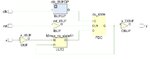
             +-----+
             |     |
     a1----- |     |
             |     |-------- y
     a2----- |     |
             |     |
             +-----+
                 |
         c-------+
Code VHDL - [expand]
             +-----+
             |     |
     X ----- |     |
             |     |--------D
     X'----- |     |
             |     |
             +-----+
                 |
+------ YAs I said and based on what we have learned, a 2-LUT has 3 inputs as I show in my previous post.
 a b | c
-----+-------
 0 0 | f(0,0)
 0 1 | f(0,1)
 1 0 | f(1,0)
1 1 | f(1,1)He is confusing LUT with MUX. Look in post #1 what is the name of the LUT: MmuxYour instructor is misleading you if this is what you were told...
A two input LUT does this
He is confusing LUT with MUX. Look in post #1 what is the name of the LUT: Mmux