Continue to Site

Welcome to EDAboard.com

Welcome to our site! EDAboard.com is an international Electronics Discussion Forum focused on EDA software, circuits, schematics, books, theory, papers, asic, pld, 8051, DSP, Network, RF, Analog Design, PCB, Service Manuals... and a whole lot more! To participate you need to register. Registration is free. Click here to register now.

Analog 4-20ma conditioning circuit

Status
Not open for further replies.

Mozaaljh

Newbie level 4
Joined
Feb 7, 2017
Messages
5
Helped
1
Reputation
2
Reaction score
1
Trophy points
3
Activity points
38
We found this circuit in one of our transducer boards .. which converts the analog 4-20ma signal to some voltage for the ADC module of the microcontroller .. As the transducer is not working any more .. we are trying to fix it and are unaware of the output voltage of the opamp . We tried the superposition method but we are still unable to synthesise the circuit..

The image of the circuit attached
Untitled.jpg
 
Last edited by a moderator:

Hi,

As far as I can see (with just a quick view).

It is a 47 Ohms measurement resistor.
It gives 0...940mV.
Then the rest is a difference amplifier with gain of 2.7.
Giving an output range of 940mV x 2.7 = 2.538V.

The problem is, that the output voltage reference is the low side of the input signal.

I assume that this node is connected to GND somewhere, but not shown in the circuit diagram.

Klaus
 

That is correct, they are using the low side of the input signal as a virtual ground.
An expecting that the opamp's CMRR will take care of it. A reasonable expectation within certain limits.
 

Vout :=(R5*R1*R2+R3*R1*R2)/(R2*R3+R4*R3+R1*R3)*I_loop;

//Test//
R1:=47
R2:=27E3
R3:=10E3
R4:=10E3
R5:=27E3
I_loop:=20E-3

Vout=[2.5348]
 

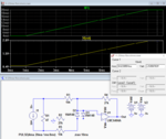
Here's an LTspice simulation of the (slightly) modified circuit which matches the calculations as expected.
As noted by Klaus there is a ground problem; the circuit won't work as shown.
I had to remove the 27k resistor, R2, from the minus side of the input signal and connect it to ground.
This allows the circuit to operate as a proper differential circuit and provide a path to ground for the op amp input bias current.
This connection still allows the current input source to float, as it typically does in 4-20mA systems.

Capture.PNG
 
Last edited:

That is correct, they are using the low side of the input signal as a virtual ground.
An expecting that the opamp's CMRR will take care of it. A reasonable expectation within certain limits.

Will you please elaborate on the CMRR part??

thank you.
 

Hi,

In opposite to schmitt trigger I don´t think the circuit generates a good CMRR.
Only a difference amplifier circuit (or INA circuit) generates good common mode rejection.

I didn´t calculate or simulate it, but I assume common mode voltage is amplified with a gain of (close to) -2.7.

A true difference amplifier could attenaute common mode voltage with a gain of +/- 0.001 or even better.
With a bit of re-arrangement of the device connections you could get a true difference amplifier. But the existing circuit is not.

There are plenty of true difference amplifier circuits around. Look for them.

Klaus
 

We found this circuit in one of our transducer boards .. which converts the analog 4-20ma signal to some voltage for the ADC module of the microcontroller .. As the transducer is not working any more .. we are trying to fix it and are unaware of the output voltage of the opamp . We tried the superposition method but we are still unable to synthesise the circuit..

The image of the circuit attached
View attachment 137442

It has to do with the CMRR...
Did you resolve it yet??
 

Status
Not open for further replies.

Similar threads

Part and Inventory Search

Welcome to EDABoard.com

Sponsor

Back
Top