Continue to Site

Welcome to EDAboard.com

Welcome to our site! EDAboard.com is an international Electronics Discussion Forum focused on EDA software, circuits, schematics, books, theory, papers, asic, pld, 8051, DSP, Network, RF, Analog Design, PCB, Service Manuals... and a whole lot more! To participate you need to register. Registration is free. Click here to register now.

SCR Bridge Control - Is my Circuit Correct ?

Status
Not open for further replies.
There was a bug in the circuit posted in #120. It was working as controlled half wave rectifier. I am fixing it. I will post the new circuit soon. It is only simulation problem. The AC Voltage source connected to SCR Bridge has one end grounded and that is the problem. Have to use two Sine sources for SCR Bridge.

- - - Updated - - -

Edit:

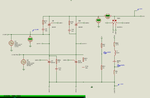
Here is the fixed Simulation file and Simulation Results. Now it is working as controlled bridge rectifier. Please check the graphs and tell me if they are correct, especially for RL Load.
 

Attachments

  • SCR Bridge Control - Proteus Simulation And Results.rar
    1.8 MB · Views: 64

Here is the final Proteus Simulation and Proteus Simulation Result of Single Phase Fully Controlled Rectifier. There is a chassis connection in the SCR circuit. It should not be used in the real hardware. It is only for simulation. Actually it is not required for realtime simulation but is required to plot graph of current as it is a requirement for the current probes to work. For realtime simulation, you can remove the chassis connection and simulate.

Thank you all. This completes the project.

I will post the code soon.
 

Attachments

  • Single Phase Fully Controlled Rectifier.rar
    1.1 MB · Views: 74

How to get Inverting mode operation in Single Phase Fully Controlled Rectifier ? That is when alpha is greater than 90 degree then output should be negative. Load will be DC Motor.
 

How to get Inverting mode operation in Single Phase Fully Controlled Rectifier ? That is when alpha is greater than 90 degree then output should be negative. Load will be DC Motor.
It will have some positive voltage and some negative voltage due to the inductive nature of the load... review post #64.
 

No, Inverter mode operation is different. See attached document page nos. 1 to 6. I have to implement this in Simulation and also hardware. Should I use a H-Bridge to switch the load connection to motor.

As shown in page 5 I should get for alpha > 90 the output should be negative and for alpha less than 90 the output should be positive that is for aolpha < 90 it should work as rectifier and for alpha > 90 it should work as inverter.

How to achieve this ?
 

Attachments

  • Lab_no_9_c1.pdf
    258.4 KB · Views: 78

No, Inverter mode operation is different.
I see no difference. It works the same as in post #64. So your problem is already solved.

The only point of that document is the load acting as an active load (generator and the voltage source as load) or passive load (simple receiver), nothing more.
From a circuit point of view, no one cares if a motor spins clockwise or counterclockwise. The connection in that schematic is that way probably because they wanted to spin the motor in a specific way.
 

The said "inverting mode" is using additional switches to reverse the SCR bridge output polarity. Your circuit according to post #122 doesn't have it. Your circuit supports 2-quadrant operation, the circuit with additional switchover 4-quadrant.
 

@FvM

What changes I have to reverse the polarity of motor and when ? Should I use a Mosfet H-Bridge at the output of SCR bridge to reverse the direction of motor connection to SCR bridge ?

If yes, what changes I have to make in code ?

I need to get positive voltage for alpha between 0 and 90 degree and negative voltage (on multimeter) for alpha between 90 and 180 degree.
 

I believe, everything is well explained in the lab instructions.

I suggest to start with the quadrant explanation in Fig. 9.4. and consider which operation modes should be supported by your design (positive and negative speed, motor and braking mode?).
 

@FvM

Ok.

The student has to show output for DC Motor load. His SCR Bridge output is 34V DC and hence he is using 3x 12V 500mA DC Motors in series. He has to show only the signal in which for alpha between 0 and 90 degree the output should be positive and for alpha between 90 and 180 degree he has to show the negative output. Only this much is needed. Breaking is not needed. Can I use L293D for driving the motors ? Vs of L293 will be provided 34V DC output from SCR bridge. VCC and EN1 pin of L293D will be connected to +5V DC. IN1 and IN2 pins will be connected to PIC output pins. OUT1 and OUT2 pins of L293D will be connected to motor (motors in series). Will this work ?

How should be the firing for 4 quadrant operation ?

This is the circuit which I made. Will this work ?
 

Attachments

  • 1PFCR.PDF
    175.9 KB · Views: 61
Last edited:

As discussed in the lab instructions, alpha > 90° is associated with braking operation. For the two quadrant circuit (without switchover), negative voltage and alpha > 90° can only occur if the motor is externally driven in reverse direction (n < 0).

You say, you don't want braking, so you apparently intend motor operation in first and third quadrant, motor actively driven forward and reverse. Motor operation in third quadrant means voltage has to be inverted by a switchover circuit, alpha is still < 90°.

Instead of a separate switchover, the previously discussed bidirectional 8-SCR-circuit could be used.

Your insisting on alpha > 90° makes me wonder if the project specification is clear at all?
 

Ok. I will ask student what he exactly needs again. I will update this thread soon.

The student can't use 8 SCR Dual Converter circuit. Instructor is telling to use only 4 SCR circuit.

Can't we use a DC source in series with RL Load to demonstrate the principle ? That is using RL Edc Load.
 
Last edited:

Can't we use a DC source in series with RL Load to demonstrate the principle?
Surely. But it should be clear which real load case is actually modeled.

Otherwise the demonstration might end up "I'm connecting negative DC source to demonstrate - I don't know what"...
 

Surely. But it should be clear which real load case is actually modeled.

In Proteus ? In Proteus RL Edc Load is not working. I asked can RL Edc load be used in real hardware instead of using the setup shown in the Lab_no_9_c1.pdf page no. 11 ?


@FvM

I asked the student and he said

Instructor needs positive output voltage for alpha between 0 and 90 degree and negative output voltage for alpha between 90 and 180. Instructor has said use any setup but show these outputs. He has to use multimeter to show the voltages and also oscilloscope.

Should I use a H-bridge with a motor at the output and reverse the polarity ? or should I use a VCVS in series with a motor ?

- - - Updated - - -

I am referring the attached document page nos 19 to 24 for Inverter mode operation of SCR Bridge Rectifier. I have understood that I have to connect a DC battery in reverse polarity to RL Load or DC Motor to get the required waveforms.

What should be the Battery voltage E (E as shown in graph or Eb as shown in calculation in page no. 24) ? Should I use the calculation shown for Eb in page no. 24 to get the value of E ?
 

Attachments

  • L-10(DK)(PE) ((EE)NPTEL).pdf
    601.2 KB · Views: 57
Last edited:

There's no DC source in your recent simulation circuit, thus I can only guess what is "not working" and why.

A (negative) DC voltage source can be used to model the active load in 4th quadrant operation, which is corresponding to braking a reverse spinning motor.

I need to add a comment regarding previously asked L293 usage. L293 would enable 3rd quadrant operation, but at the same time block 2nd and 4th quadrant because it doesn't allow negative output of the SCR bridge.
 

Here is the Proteus circuit.

Also see page nos. 10 and 21 of PDF in post 134.

In page 21 is shows graph but I see for alpha < 90 output Vo is negative and for alpha > 90 the output is positive. Is the graph wrong ?

Thank you. I think I got the output. Vo in rectifier mode is 34V DC at 90 degrees. The student needs to get for alpha between 0 and 90 degrees positive Vo and for alpha between 90 and 180 negative Vo and so for alpha 90 the Vo should be 0. I used a 34V reverse polarity DC source in series with RL load. I got the required output waveforms. I will post the simulation file and simulation video. I am preparing the video.
 

Attachments

  • Circuit Clip #2.png
    Circuit Clip #2.png
    18.5 KB · Views: 65
Last edited:

34V is simply too high. Any voltage value above rectified average value of AC input will possibly fail SCR commutation. Start with 10 or 15 V.
 

Ok.

But I tested with 17V reverse connected battery and the operation was in discontinuous mode and hence to get 0V at 90 degrees I used 34V battery. How to get continuous mode operation with 15V battery ?
 

Feasibility of continuous operation has also to do with L/R time constant 50 mH/12 ohms may be too low.
 

In Proteus 50mH and 12 Ohms is used. In real hardware 50mH and 10k is used. Greater than 50mH Inductor is not available at shops at student's place. He has to show simulation tomorrow and demonstration of hardware in 3 or 4 days.

If RL time constant is increased then will I get continuous mode of operation ? or if DC Motor is used with 15V reverse connected battery can I get continuous mode of operation ? DC Motor is 3x 12V 500mA in series and I guess motor inductance is 100mH.


See attached Simulation video. It shows continuous mode operation for Edc 34V and discontinuous mode operation for Edc = 15V. I used 50mH and 12 Ohms in Proteus. I have to check with 10k R.
 

Attachments

  • Proteus Simulation Video #1.rar
    887.5 KB · Views: 45
Last edited:

Status
Not open for further replies.

Part and Inventory Search

Welcome to EDABoard.com

Sponsor

Back
Top