Continue to Site

Welcome to EDAboard.com

Welcome to our site! EDAboard.com is an international Electronics Discussion Forum focused on EDA software, circuits, schematics, books, theory, papers, asic, pld, 8051, DSP, Network, RF, Analog Design, PCB, Service Manuals... and a whole lot more! To participate you need to register. Registration is free. Click here to register now.

Transceiver Ultrasonic Sensor Problem

Status
Not open for further replies.

reeraslan

Newbie level 4
Joined
May 21, 2012
Messages
6
Helped
1
Reputation
2
Reaction score
1
Trophy points
1,283
Activity points
1,357
Hi, I am working on Ultrasonic Transceivers for my range finder project. My main goal is to achieve this project with one sensor.
Before this, I've achieved range finding with Receiver / Transmitter Sensors separately. It worked well but as I said I need to finish this with transceiver sensor.

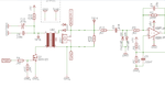
So, here is the my schematics that I draw for 1 sensor.
RF0401.png

My driver circuits works fine. It generates around 100Vp-p. But the problem is there was no any echo signal coming through amplifier circuits. I tried to bring another ultrasonic transmitter sensor that generates 40khz 20Vp-p closer to this single transducer circuits. Still, there was no any signal after R13 & D2 protection stage on my osciloscope.

Here is the another info. Amplifier circuits also works fine. How do I know? When I stop generating high voltage from Driver circuit and remove the R13 & D2, I got very clear echo signals from the output of the 1st amplifier.

Here is the scope view
DS1Z_QuickPrint2.png
Blue: My Burst trigger signal. From Signal Generator ( LABEL : PWM )
Yellow : Bursted Voltage x100 ( TP14 )
Purple : 1st Amplifier output ( TP3 )

What am I doing wrong? Why can't I see any echo? Why my protection circuits ( R13 & D2 ) blocks the echo signals?

Thanks
 

hi,
The secondary winding of the output transformer is presenting a very low impedance for the transducer, when in the receive mode.
One method used, is to connect two fast diodes in anti-parallel between the transducer and the high side of the transformer secondary
ie: SG1 2 and C of U$2
This effectively isolates the transducer from the transformer for low level echo signals.
Keep R13 and diodes D2 in circuit as per your diagram.

Try it and post your results.
E
 

I am sorry if I misunderstood you. Are you suggesting the scheme down below?
edaboard1.png
 

hi R,
No, it is like this image.
E

EDIT:
Basic sim plot from LTS, this shows the period after the TXPulse
 

Attachments

  • edaboard1.png
    edaboard1.png
    20.3 KB · Views: 135
  • A001.gif
    A001.gif
    38.9 KB · Views: 143

Hello E,

Thanx for your advice. I applied your scheme
I saw some echos but there are some problems
Here is the scope view.
IMG_20170319_162444.jpg
Yellow : Second Amplifier Output
Purple : Trigger Voltage (signal gen.)
Blue : Bursted Voltage3 (36Vp-p)

My first gain is 44 and second gain is 100
the result is weird. The gain is so huge for this application but I didn't expect that amount of voltage output. Echo is so small, Do you know why is that?
Btw there is a lot of noise on output. Trying to eliminate with C4 & C8 but still noisy.
And when I connect the serial diodes on high side of transformer, the voltage across the transducer is decreasing. It also effects echo's amplitude.

What does the high side diodes do in this scheme? I didn't get it

Thank you
 

hi,
Is your transformer tuned to 40kHz, also what is the step up ratio, primary to secondary.?

The 33pF caps across the 100k OPA feedback resistors are reducing the overall gain at 40kHz, by 6dB.

Ref the antiparallel diodes, when the TX transmission signal across the diode is greater than ~0.7v , the forward resistance is is in the order of a 500R.
As RX echo signal is usually much less that 0.7v, the diodes are effectively an open circuit, so the transducer is not loaded by the transformer winding.
I am assuming the transducer is a general purpose 40kHz type.?
Look at the two plot for the receiver when using the original caps and the lower value caps across the OPA's.
I have also reduced the value of the inter OPA caps.

E
 

Attachments

  • A001.gif
    A001.gif
    45.2 KB · Views: 125
  • A004.gif
    A004.gif
    44.9 KB · Views: 121

hi,
Is your transformer tuned to 40kHz, also what is the step up ratio, primary to secondary.?

The 33pF caps across the 100k OPA feedback resistors are reducing the overall gain at 40kHz, by 6dB.

Ref the antiparallel diodes, when the TX transmission signal across the diode is greater than ~0.7v , the forward resistance is is in the order of a 500R.
As RX echo signal is usually much less that 0.7v, the diodes are effectively an open circuit, so the transducer is not loaded by the transformer winding.
I am assuming the transducer is a general purpose 40kHz type.?
Look at the two plot for the receiver when using the original caps and the lower value caps across the OPA's.
I have also reduced the value of the inter OPA caps.

E

Thank you for your scheme again.
I did tear down this transducer and it's transformer from rangefinder modules. As my before experiments with single transducer driving circuit, I've seen 100Vp-p across the transducer from 5V primer supply. Step up ratio must be 1:10
So as I understand, It supposed to be tuned to 40khz for this transducer, But
**broken link removed**
 

Hello,

Firstly, thank you for this thread, it was quite useful.
I am interesting in design similar circuit that will use 200kHz ultrasonic sensor. Is this circuit can be applied for this?

Thank you.
 

I am interesting in design similar circuit that will use 200kHz ultrasonic sensor. Is this circuit can be applied for this?
Similar but not exactly the same. The circuit has to be adapted to the transducer impedance.
For highest bandwidth (= best time resolution), the sensor should be operated matched both during transmit and receive phase.
 

Thank you for your answer.
I understand that during transmit a matching transformer must be used. Some transformers are recomendend with some ultrasonic sensor, like in here: http://www.prowave.com.tw/english/products/sr/transf.htm. What about this transformers: http://www.murata.com/~/media/webre...tokoproducts/variablecoils/m_fsdva.ashx?la=en. Can I use them both for 40kHz and 200kHz ultrasonic sensors, since his frequency range is 0.05 to 15Mhz?

Can you explain me, using previous schematics from this thread how and with which components the matching in receive phase is achieved? If there is any tutorial or document that deal with this subject please share it with me.

I saw that there are some IC solution for ultrasonic sensors signal conditioning, like pga450-q1, PW0268, TDC1000. is there any other solutions that I am not aware of it?

Thank you.
 

Status
Not open for further replies.

Similar threads

Part and Inventory Search

Welcome to EDABoard.com

Sponsor

Back
Top