Continue to Site

Welcome to EDAboard.com

Welcome to our site! EDAboard.com is an international Electronics Discussion Forum focused on EDA software, circuits, schematics, books, theory, papers, asic, pld, 8051, DSP, Network, RF, Analog Design, PCB, Service Manuals... and a whole lot more! To participate you need to register. Registration is free. Click here to register now.

Analog switching between two sources 5V/1A and 5V/2A

Status
Not open for further replies.

Dino1400

Full Member level 1
Joined
Sep 22, 2010
Messages
95
Helped
2
Reputation
4
Reaction score
2
Trophy points
1,288
Activity points
1,941
Hello everyone,

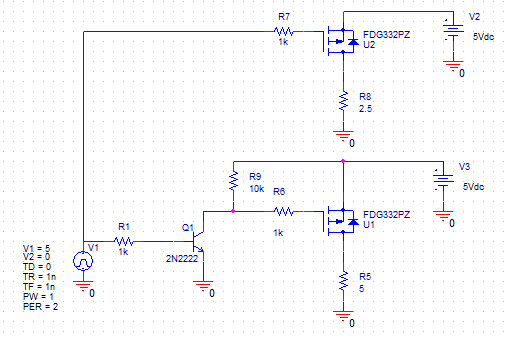
I'm trying to switch between two sources 5V/1A and 5V/2A based on a decision circuit (a compactor: if high close 5V/1A else close 5V/2A).

can anyone have an idea of how to design these switches (could ne some NPN an PNP).

please see attached picture.

Thank you in advance.

IMG_5070.JPG
 

Depends on how fancy you want to be. Do you need to worry about both switches being on momentarily during a switch-over? You could use a P-channel mosfet and drive the gate with your comparator output.
 

the first thing that came to my mind is to use either PNP+NPN or N-channel +P-channel but I'm not sure how reliable this idea.
I have attached both approaches please provide me with your though and comment and it there is a better approach i will appreciate your help IMG_5071.JPGIMG_5072.JPG

- - - Updated - - -

Thank you for your prompt replay. Is AM1 and AM2 connected to the charger box, can you send me some explanation of this circuit looks very interesting.
 

Those are a little too simplistic. For one thing, your n-ch fet will always conduct because of its intrinsic diode. Use two p-channels and two complimentary gate drives
 

I'm thing about using a part from Texas Instruments
TS5A3157 10-Ω SPDT Analog Switch
I just need to figure out how to use it in my circuit.

Can you provide a drawing for your suggestion or if you have used something before like TS5A3157 or simular part.

Thank you again
 

I used 10 V for the charger since the PMOS needs high level gate drive. You need to use the logic gate types.
 

10 ohm?
Do the math....how much voltage will you drop at 2 amp current with a 10 ohm switch?
 

I'm thing about using a part from Texas Instruments
TS5A3157 10-Ω SPDT Analog Switch
I just need to figure out how to use it in my circuit.

Can you provide a drawing for your suggestion or if you have used something before like TS5A3157 or simular part.

Thank you again

Good luck, you'll be dissipating 40 watts across that sucker.
 

post #2 is a good proposal i just needed some more details and explanation.
I also Asked If anyone asked have TI TS5A3157 SPDT Analog Switch or SGM3157YC6 which is Capture3.PNGCapture2.PNGCapture.PNGbased on MOSFET swiching in one IC package.


Hello all,

I'm posting a circuit that I thinking to use to switch between two power supplies.
Please If you have any comment or better suggestion I will really appreciate that.

Thank you in advance.
Dino

Capture11.jpg
 

Hello all,

I'm posting a circuit that I thinking to use to switch between two power supplies.
Please If you have any comment or better suggestion I will really appreciate that.

Thank you in advance.
Dino

View attachment 137057
Sure. Did you give up on trying to design a more reliable, less expensive proper solid-state solution?
 
I have not give I just talk to colleague of mine said to keep it simple as you can. I like to use different solution of course I like the proposal from post #2.

I attached here again with a minor modification.

IMG_5085.JPG
 

Those MOSFETs should be P channel and logic level... if you want it to work. What is the comparator's output voltage ?
The FDG332PZ, P channel mosfets from post #2 looks OK.
 
Last edited:

thank you for your response, the comparator's voltage should be 5V.
 

thank you all
and special thanks to E-design and Catam
 

Status
Not open for further replies.

Part and Inventory Search

Welcome to EDABoard.com

Sponsor

Back
Top