Continue to Site

Welcome to EDAboard.com

Welcome to our site! EDAboard.com is an international Electronics Discussion Forum focused on EDA software, circuits, schematics, books, theory, papers, asic, pld, 8051, DSP, Network, RF, Analog Design, PCB, Service Manuals... and a whole lot more! To participate you need to register. Registration is free. Click here to register now.

Relationship between Q factor and the coupling factor of two wireless coils

Status
Not open for further replies.
Measure the coupling at the distance you want to operate the coils to know where we are.
You will have to get rid of those parasitics because you do not know their values. Place output and input buffer (to reduce those 50 ohms from the source).

Hi CataM,
(1) how can I measure the coupling at the specific distance? Are you talking about measuring the peak to peak Vrx and Vtx? (2) For the buffers I can use, since they are dealing with pure AC signal, does that mean I need to use dual rail (for example, +/-5V vcc) opamp? It is OK for me to place one in the Tx coil, but it is hard to get one in the Rx side. How can I solve this in the output side?
Thank you!
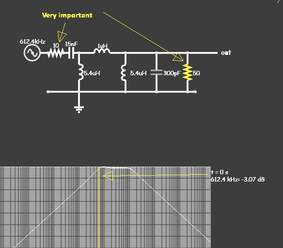
 

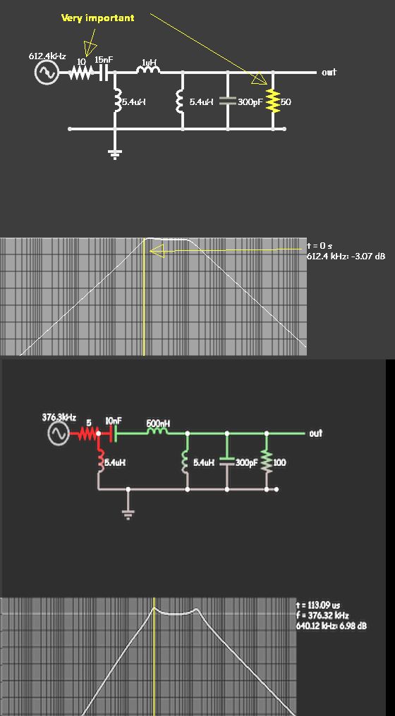
This works by impedance ratios. Can you make this work?

Note the source is 10 Ohms not 50. so the ratio of Load to source is 5:1 while coupling factor is 1:5 with a wide tolerance since it is low Q.

C1 on left controls 1st breakpoint and small C2 on right controls 2nd breakpoint with equal inductor coils.

Use low capacitance 10:1 probe to scope.

5385460000_1489697035.jpg


adverse variations
6035832300_1489697983.jpg
 

Attachments

  • 1.jpg
    1.jpg
    54.4 KB · Views: 66
Last edited:

This works by impedance ratios. Can you make this work?

Note the source is 10 Ohms not 50. so the ratio of Load to source is 5:1 while coupling factor is 1:5 with a wide tolerance since it is low Q.

C1 on left controls 1st breakpoint and small C2 on right controls 2nd breakpoint with equal inductor coils.

Use low capacitance 10:1 probe to scope.

5385460000_1489697035.jpg


adverse variations
6035832300_1489697983.jpg

Thank you SunnySkyguy!
(1) Am I supposed to fix the 10 Ohm and 50 Ohm in two ends and then tune C1 and C2 towards the target? Because I have not understand this circuit yet, only seeing the influence of C1 and C2 to the breakpoints.
(2) My function generator has 50Ohm terminator, is it supposed to be taken into consideration? If so, must I use the buffer to isolate function generator and the 10 Ohm resistor?
 

(1) how can I measure the coupling at the specific distance? Are you talking about measuring the peak to peak Vrx and Vtx?
I am referring to the magnetic coupling factor "k" (not voltage ratio). https://www.daycounter.com/LabBook/Mutual-Inductance.phtml

(2) For the buffers I can use, since they are dealing with pure AC signal, does that mean I need to use dual rail (for example, +/-5V vcc) opamp? It is OK for me to place one in the Tx coil, but it is hard to get one in the Rx side. How can I solve this in the output side?
You can use simple emitter follower. it depends on how handy does they come for you ..

You have to use buffers if necessary, which means, we have gave our opinion based on the information you provided (which is very little, and every time you show a schematic is different than the last one) and then you have to decide because you know your full application and you are going to be the responsible for it after all.
 
Last edited:
  • Like
Reactions: bhl777

    bhl777

    Points: 2
    Helpful Answer Positive Rating
There are different ways to describe the parameters of coupled inductors, and many ways to measure it. I don't think that you necessarily need a buffer for the measurement.

The problem is to decide which parameters you want to measure and to understand how can they be derived from your primary measurement values, e.g. voltage and current values or resonance frequencies.

Hi FvM, what I want is to have a decent Vpp sine signal at the Rx coil in the target frequency range when I send a pure sine signal from the function generator to the Tx coil. One simple example, if I send 1V Vpp sinusoidal signal at the frequency of 1MHz, 3MHz and 5MHz at different time, am I able to generate a sine voltage at the Rx side with Vpp close to 1 V (greater or with minimum attenuation) ?
 

you cannot use sig gen output, it must be buffered such as emitter follower with series R if you want to perform my design to match your specs, otherwise change your specs
 

you cannot use sig gen output, it must be buffered such as emitter follower with series R if you want to perform my design to match your specs, otherwise change your specs

Hi SunnySkyguy, I used the buffer and can get the correct sine signal in all frequency ranges. Thank you!
However, I still need to change most of the components' values to get the optimal performance. This is my current setup:
transient_new.png
I started from the values in your schematic but have to tune it to the values above to get a resonable bode plot. In addition, I tried emitter follower but has some problem in getting the corrected shift up sine wave in its output. So I used the opamp buffer.
This is the bode plot I have. The double peak within the target frequency range is shown, but most of the gain is less than 0dB.
bode2.JPG
My questions are:
(1) Is it possible to shift up the gain between 1MHz to 5MHz above 0dB
(2) how can I make this band flatter?
(3) I did try 50 Ohm at the secondary side but using that one the right peak almost cannot be observed. Is there any potential problem in my current setup?
Thank you!
 

The distance is fixed to 1 cm, or you can vary it as you want? You can vary the distance to where is best, or 1 cm is fixed?
What is the coupling factor at the distance you want to operate?
 

The distance is fixed to 1 cm, or you can vary it as you want? You can vary the distance to where is best, or 1 cm is fixed?
What is the coupling factor at the distance you want to operate?

Hi CataM, I always fixed the distance to 1cm. More generally, I want it to operate well in all the distance <=1cm. Thank you!
Sorry I have not measured the coupling factor yet, will try soon according to the link provided by you before.
 

The distance is fixed to 1 cm, or you can vary it as you want? You can vary the distance to where is best, or 1 cm is fixed?
What is the coupling factor at the distance you want to operate?

Hi CataM, I have an additional question regarding the possibility of this circuit. The existing circuit is used for my data coil operation, while I have a 6.78MHz power coil in this system. I used coplanar structure to place both Rx data coil and Rx power coil and found no noise coupling in the Rx data coil without including any specific filter to reject the noise from the power coil. It is good, but I am not confident if in some scenarios the noise coupling from the 6.78MHz power coil can impact the operation when data coil is between 1MHz to 5Mhz.
My questions are:
(1) do you think it could be a problem when my frequency separation between the data coil and power coil is only 6.78MHz-5Mhz=1.78MHz?
(2) Is there any quick way to modify this flat band circuits, by adding one or two poles around 6MHz to make a steep attenuation when the frequency is beyond 5MHz? So we will have much more attenuation in 6.78MHz. I was thinking of using the higher order active filter. However, it is difficult in processing the pure AC signal as its input when the opamp is supplied by 0V to 5V.
(3) If the frequency separation is not enough and no quick fix can be done. I am thinking to redesign my power coil and let it operate in 13.56MHz. From the existing bode plot, it has around 20dB attenuation between 5MHz and 13.56MHz, which looks like reasonable to serve as an LPF to reject the coupling noise from the power coil, is this correct?
Thank you!
 

It is good, but I am not confident if in some scenarios the noise coupling from the 6.78MHz power coil can impact the operation when data coil is between 1MHz to 5Mhz.

(1) do you think it could be a problem when my frequency separation between the data coil and power coil is only 6.78MHz-5Mhz=1.78MHz?
In some case scenarios when the power coil is brought near the data coil, even when coils are coplanar, the coupling will influence the data coil. I guess some shielding would protect data coil and power coil but I know very little about that.
You may want to take a look at the Chapter 10, section 10.3 Shielding effectiveness : Near field sources, from the book Introduction to Electromagnetic compatibility by Clayton Paul.

(2) Is there any quick way to modify this flat band circuits, by adding one or two poles around 6MHz to make a steep attenuation when the frequency is beyond 5MHz? So we will have much more attenuation in 6.78MHz. I was thinking of using the higher order active filter. However, it is difficult in processing the pure AC signal as its input when the opamp is supplied by 0V to 5V.
Additional filters after the receiver coil would not impede the receiver coil to pick up the 6 MHz noise. If you want to reject it after it was picked up in order to prevent it from reaching the other circuit stages, then I would say a passive band-reject filter is appropriate in this case, but make sure it is appropriately buffered in order to not disturb the receiver and the post stages (stages after the receiver).

(3) If the frequency separation is not enough and no quick fix can be done. I am thinking to redesign my power coil and let it operate in 13.56MHz. From the existing bode plot, it has around 20dB attenuation between 5MHz and 13.56MHz, which looks like reasonable to serve as an LPF to reject the coupling noise from the power coil, is this correct?
That would be an option if 13.56 MHz still performs well for your application.
 
  • Like
Reactions: bhl777

    bhl777

    Points: 2
    Helpful Answer Positive Rating
In some case scenarios when the power coil is brought near the data coil, even when coils are coplanar, the coupling will influence the data coil. I guess some shielding would protect data coil and power coil but I know very little about that.
You may want to take a look at the Chapter 10, section 10.3 Shielding effectiveness : Near field sources, from the book Introduction to Electromagnetic compatibility by Clayton Paul.


Additional filters after the receiver coil would not impede the receiver coil to pick up the 6 MHz noise. If you want to reject it after it was picked up in order to prevent it from reaching the other circuit stages, then I would say a passive band-reject filter is appropriate in this case, but make sure it is appropriately buffered in order to not disturb the receiver and the post stages (stages after the receiver).


That would be an option if 13.56 MHz still performs well for your application.

Thank you CataM. I will read the book from Paul about the shielding.
Regarding your answer in question 3: theoratically, should we expect a 13.56MHz WPT introduce less noise coupling than a 6.78MHz for my case? If so, is it because we see much more attenuation in the bode plots?
Thank you!

- - - Updated - - -

Thank you CataM. I will read the book from Paul about the shielding.
Regarding your answer in question 3: theoratically, should we expect a 13.56MHz WPT introduce less noise coupling than a 6.78MHz for my case? If so, is it because we see much more attenuation in the bode plots?
Thank you!

Hi CataM, regarding the shield, if I am using 13.56MHz power coil, can I use the RF shield for RFID application for my board? I found a lot of RF shield for RFID application, which indicates 13.56MHz (such as “WE-FAS RFID Flexible Absorber Sheet” in https://katalog.we-online.de/en/pbs/WE-FAS-RFID?m=t&sq=rf+shield&sp=https%3A%2F%2Fwww.we-online.com%2Fweb%2Fen%2Fwuerth_elektronik%2Fsearchpage.php%3Fsearch%3DRF%2Bshield&_ga=1.249364743.10007329.1457366634). Do you think can I use this sheet around the power coil to minimize its interference with the other parts of the circuits?
Thank you!
 

Regarding your answer in question 3: theoratically, should we expect a 13.56MHz WPT introduce less noise coupling than a 6.78MHz for my case? If so, is it because we see much more attenuation in the bode plots?
It will introduce more attenuation in the frequencies in between 5 MHz and 13.56 MHz, but I think more or less the same at 13.56 MHz as it would be for the power coil operating at 6.78 MHz. It is because of the bode plot but not the Bode plot you have shown, instead, the Bode plot between power coil and data coil.
As you have seen by adjusting this coupled data coils, it will depend on both the power coil impedance, and data coil impedance how much of attenuation you will have.

Hi CataM, regarding the shield, if I am using 13.56MHz power coil, can I use the RF shield for RFID application for my board? I found a lot of RF shield for RFID application, which indicates 13.56MHz (such as “WE-FAS RFID Flexible Absorber Sheet” in https://katalog.we-online.de/en/pbs/WE-FAS-RFID?m=t&sq=rf+shield&sp=https%3A%2F%2Fwww.we-online.com%2Fweb%2Fen%2Fwuerth_elektronik%2Fsearchpage.php%3Fsearch%3DRF%2Bshield&_ga=1.249364743.10007329.1457366634). Do you think can I use this sheet around the power coil to minimize its interference with the other parts of the circuits?
I can not talk about shielding because I know very little about it. Maybe you should ask this on the RF section or Electromagnetic design section.
 
  • Like
Reactions: bhl777

    bhl777

    Points: 2
    Helpful Answer Positive Rating
It will introduce more attenuation in the frequencies in between 5 MHz and 13.56 MHz, but I think more or less the same at 13.56 MHz as it would be for the power coil operating at 6.78 MHz. It is because of the bode plot but not the Bode plot you have shown, instead, the Bode plot between power coil and data coil.
As you have seen by adjusting this coupled data coils, it will depend on both the power coil impedance, and data coil impedance how much of attenuation you will have.


I can not talk about shielding because I know very little about it. Maybe you should ask this on the RF section or Electromagnetic design section.

Thank you CataM. I am going to try bode test in a coplanar structure to how the AC injection in the power coil can cause the change of data coil. If there is no big difference in the Bode plot, can we conclude from the noise coupling perspective, either frequency in the WPT is OK? Thank you!
 

Thank you CataM. I am going to try bode test in a coplanar structure to how the AC injection in the power coil can cause the change of data coil. If there is no big difference in the Bode plot, can we conclude from the noise coupling perspective, either frequency in the WPT is OK? Thank you!

Hi CataM, I did the Bode measurement according to your advice. My setup is as follows and Rx data coil and Rx power coil are in the same plane. If we just look at this bode plot (Vout/Vin), we should expect a better attenuation to 13.56MHz power link noise at the data coil than the case with 6.78MHz power link noise. Do you think my measurement results make sense? Or is there anything wrong in my power link setup?
My power coils (both Tx and Rx) are 760308103307 from Wurth.
Thank you!
bode for noise coupling.png
 
Last edited:

Unfortunately the hidden parts of your schematic contain the cause for the actually observed magnitude diagram (e.g. capacitive and possibly resistive load). As in previous diagrams, the generator impedance isn't shown.

I won't be able to derive anything from this measurement.
 

Unfortunately the hidden parts of your schematic contain the cause for the actually observed magnitude diagram (e.g. capacitive and possibly resistive load). As in previous diagrams, the generator impedance isn't shown.

I won't be able to derive anything from this measurement.

Thank you FvM. If we do not try to derive anything from this bode test, but just talk about the general case, what is the considerations regarding the noise coupling issue from the power link to the data link? In my case, my data link has amplitude between 1MHz to 5MHz. And I have a choice to use either 6.78MHz power link or 13.56MHz power link. From the theory, which one could be more preferrable? Thank you!
 

Not quite sure why you want high frequency power link although the coils are optimized for Qi 100 kHz range? 13.56 MHz is an internationally regulated ISM frequency may be preferred over 6.78 MHz, don't know what are the applicable standards in your region. Larger distance to 5 MHz eases selective filtering.
 

Not quite sure why you want high frequency power link although the coils are optimized for Qi 100 kHz range? 13.56 MHz is an internationally regulated ISM frequency may be preferred over 6.78 MHz, don't know what are the applicable standards in your region. Larger distance to 5 MHz eases selective filtering.

Hi FvM, thank you for your advise. My application is a biomedical circuits for implant purpose. Therefore, we have to use 6.78MHz or 13.56MHz power link.
For the selective filtering, as you already see in thread #48, the data link itself can reject some of the noise in the frequency at 13.56MHz. I guess this is not enough. If we look at this post answered by you (https://www.edaboard.com/threads/364923/#post1562652), I can see the noise coupling at the Rx data coil with both 6.78MHz power link and 13.56MHz power link. Do you have any suggestion how can I design extra filtering circuits in the data link to furthur reject the noise coupling from power link?
Thank you!
 

Status
Not open for further replies.

Similar threads

Part and Inventory Search

Welcome to EDABoard.com

Sponsor

Back
Top