Continue to Site

Welcome to EDAboard.com

Welcome to our site! EDAboard.com is an international Electronics Discussion Forum focused on EDA software, circuits, schematics, books, theory, papers, asic, pld, 8051, DSP, Network, RF, Analog Design, PCB, Service Manuals... and a whole lot more! To participate you need to register. Registration is free. Click here to register now.

MOSFET Driver Output Problem

Status
Not open for further replies.

nsguiamano

Junior Member level 1
Joined
Feb 5, 2014
Messages
19
Helped
0
Reputation
0
Reaction score
0
Trophy points
1
Activity points
170
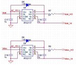
I'm using an IRS2117 MOSFET Driver connected in the circuit below
Capture.JPG

I'm using a DC power supply to provide the 15V Vcc, and 1uF capacitors for both circuits.
The problem is, attaching an input signal from a function generator (square wave, 0-5V, 1kHz), the U8 output is always at 9.8V, and U9 output at 1V.

I've tried the following to solve the problem but no luck:
1. Replace the driver itself
2. Use polarized and non-polarized caps
3. Probe negative at both ground and Vs
4. Removed all other components surrounding the circuit

I've used IRS21867 (high side-low side version of this IC) before and just followed the datasheet schematic like what I did now and didn't have a problem making that IC work.

Any though on what else I should be doing?
 

The circuit is incomplete and doesn't work without a load that pulls Vs node to ground.
 
Hi! Will that also explain the different outputs of the 2 drivers?
 

Hi,

No, but this is the next error: VIH needs to be way more than 5V. Recommended more than 9.5V....VCC.

Klaus
 

Hi,

No, but this is the next error: VIH needs to be way more than 5V. Recommended more than 9.5V....VCC.

Klaus

Hi!

That seems to forfeit the purpose of the driver? My signal is coming from a microcontroller, therefore the maximum I can raise the signal to is 5V.

Also, I realized that U8 and U9 have different outputs cause U8's load is not yet connected which should explain the 9.8V output.

However, considering that U9 does have a load attached and is still not switching at the output confuses me.

For now I will put a resistor (I guess around 100k) between Vs and ground so that my drivers will always have a standby load.
 

100k load is hardly sufficient. Read the datasheet, Vb quiescent current must flow somewhere, maintaining the Vb-Vs minimal supply voltage. But you can try, if Vb -Vs is > VBSUV+,max (9.6V), everything should be O.K.

It would be helpful to see the complete application respectively test circuit instead of a snippet.

Hi, here's the rest of the output for the circuit. I realized that my SCR isn't turned on when I was testing so Vs had no effective path to ground.

Capture.JPG
 

Hi,

I can´t see how this should and can operate.

In my eyes there are a lot of design errors.

What´s D10, D11, D3 for?
How do you think that MOC is operating?
What is the SCR (what type) good for?
I even can´t see how your MOSFETs should be operated.

Klaus
 

Hi,

I can´t see how this should and can operate.

In my eyes there are a lot of design errors.

What´s D10, D11, D3 for?
How do you think that MOC is operating?
What is the SCR (what type) good for?
I even can´t see how your MOSFETs should be operated.

Klaus

For simplicity, my current circuit only consists of the driver circuit connected to a mosfet with
Ho > G
15V > D
Vs > S
And a resistor connected between Vs and Ground.
Vin to my driver is coming from a function generator. However, powering up the circuit, and probing Ho with respect to Vs, there is to no output.
 

Status
Not open for further replies.

Part and Inventory Search

Welcome to EDABoard.com

Sponsor

Back
Top