Audioguru
Advanced Member level 7
- Joined
- Jan 19, 2008
- Messages
- 9,455
- Helped
- 2,151
- Reputation
- 4,302
- Reaction score
- 2,008
- Trophy points
- 1,393
- Location
- Toronto area of Canada
- Activity points
- 59,701
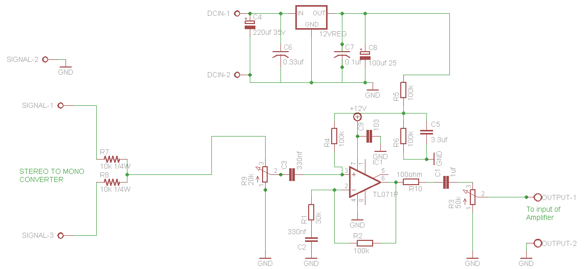
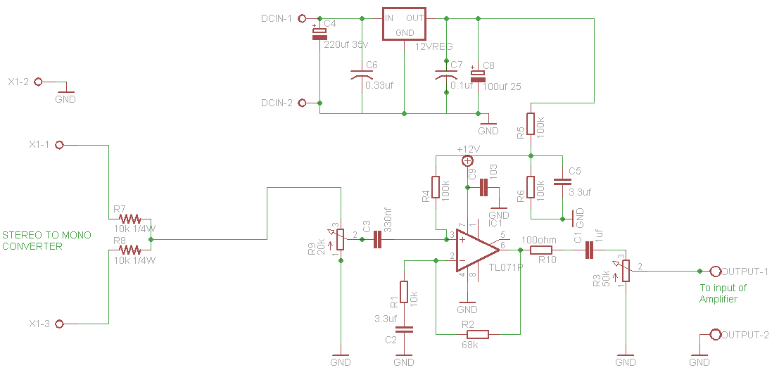
Your preamp should work fine with line level input audio.