Continue to Site

Welcome to EDAboard.com

Welcome to our site! EDAboard.com is an international Electronics Discussion Forum focused on EDA software, circuits, schematics, books, theory, papers, asic, pld, 8051, DSP, Network, RF, Analog Design, PCB, Service Manuals... and a whole lot more! To participate you need to register. Registration is free. Click here to register now.

transfer function of switched capacitor low pass filter

Status
Not open for further replies.

amir_rch

Junior Member level 3
Joined
Dec 10, 2015
Messages
26
Helped
1
Reputation
2
Reaction score
1
Trophy points
3
Activity points
205
hello everybody
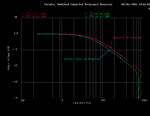
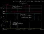
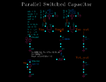
Figure below shows a switched capacitor low pass filter. Implemented this circuit in Cadence.Used NMOS transistors for the two switches.I want By changing the input frequency obtain the amplitude and phase of the transfer function of the filter.
Untitled.jpg
 

That is not a low-pass filter.
Assuming there is a full transfer of charge for each clock pulse, it simply reduces the signal by the ratio of C1/(C1+C2).
 

1.jpg2.jpg
Dear crutschow :
1-With Considering the book CMOS analog circuit design of allen, this circuit is low pass filter.
2-I need to calculate the transfer function in cadence , but i dont know what is the way .
 
Yes, it's a first order time discrete low-pass.

You get the z-domain transfer function by calculating the difference equations for Vo. The parameters of the continuous time equivalent circuit are obtained by a bilinear transformation. An example for the first order low pass filter is calculated here https://en.wikipedia.org/wiki/Bilinear_transform

For C1 << C2, the time constant of the equivalent continuous low-pass is Ts*C2/C1 respectively ωc ≈ fs*C1/C2
 

Attachments

  • Parallel_SCF_freq.png
    Parallel_SCF_freq.png
    25.1 KB · Views: 219
  • Parallel_SCF_time.png
    Parallel_SCF_time.png
    25.2 KB · Views: 253
  • Parallel_SCF.png
    Parallel_SCF.png
    28.7 KB · Views: 219
Last edited:
Dear pancho_hideboo , thanks alot for your help ;
1- can you tell me more about Shooting-Newton-PSS/PAC Analysis.i cant find PSS/PAC setting in this link "N path filter design" for cadence virtuoso.
2-in this image , input source is defined as port , what is the resistance of port ?
Parallel_SCF.png
 

1- can you tell me more about Shooting-Newton-PSS/PAC Analysis.i cant find PSS/PAC setting in this link "N path filter " for cadence virtuoso.
Surely see Netlist. All informations are there.

2-in this image , input source is defined as port , what is the resistance of port ?
It is "analogLib/vsource" not "analogLib/port".
Again surely see Netlist above.
 
Last edited:
dear pancho_hideboo ;
if Vin : a sine wave voltage to the input (Vi) with a frequency of 1 kHz and an amplitude of 0.5 V superimposed on a 0.5 V DC voltage and switches is NMOS with a square wave voltage with amplitude of 1.2V. The switching
frequency of the switches is 20 kHz.why my simulink is diffrent with your answers?
how you can calculate FFT for this circuit and How do you interpret this FFT?
 

if Vin :
a sine wave voltage to the input (Vi) with a frequency of 1 kHz and an amplitude of 0.5 V superimposed on a 0.5 V DC voltage

and switches is NMOS with a square wave voltage with amplitude of 1.2V.

The switching frequency of the switches is 20 kHz.
You can not understand simulation at all.

If you invoke PSS/PAC, Vin is a small signal.
Can you understand small signal ?
Code:
Vimpulse1 (Vin 0) vsource dc=5 type=dc pacmag=1

Can you understand a concept of impulse respose surely ?
For impulse response analysis, you have to invoke Transient Analysis, here Vin is one pulse not sinusoidal.
Code:
Vimpulse1 (Vin 0) vsource dc=5 type=pulse delay=td_in val0=0 val1=1 \
        period=1K rise=tr_in fall=tf_in width=tw_in

If you want do PSS/PAC and Tran at once, Vin is following.
Code:
Vimpulse1 (Vin 0) vsource dc=5 type=pulse delay=td_in val0=0 val1=1 \
        period=1K rise=tr_in fall=tf_in width=tw_in pacmag=1

why my simulink is diffrent with your answers?
I can not know your situation.

how you can calculate FFT for this circuit
and How do you interpret this FFT?
Again,
If you invoke PSS/PAC, Vin is a small signal.
If you invoke Transient Analysis, Vin is one pulse.

Code:
// Generated for: spectre
// Generated on: Apr 23 21:16:27 2001
// Design library name: MyTestLib
// Design cell name: Parallel_SCF
// Design view name: schematic
simulator lang=spectre
global 0
parameters tw_in=1u tw=3u tr_in=0.05u tf_in=0.05u tf=0.05u dv=1e-3 VL=-0.5 \
    VH=0.5 tr=0.05u tperiod=12.5u td1=1u k=2 \
    td_in=(td1+tr+tw)-(tr_in+tw_in/2) td2=td1+(tperiod-k*(tr+tw+tf))

// Library name: MyTestLib
// Cell name: Parallel_SCF
// View name: schematic
Vimpulse2 (net22 0 Vin 0) vcvs gain=1.0
Vimpulse1 (Vin 0) vsource dc=5 type=dc delay=td_in val0=0 val1=1 period=1K \
        rise=tr_in fall=tf_in width=tw_in pacmag=1
R1 (Vct_out net22) resistor r=25K
SW1 (Vin Vmid phi1 0) relay vt1=(VL+VH)/2-(dv) vt2=(VL+VH)/2+(dv) \
        ropen=10M rclosed=10m
SW2 (Vmid Vsc_out phi2 0) relay vt1=(VL+VH)/2-(dv) vt2=(VL+VH)/2+(dv) \
        ropen=10M rclosed=10m
Phai_2 (phi2 0) vsource type=pulse val0=VL val1=VH period=tperiod \
        delay=td2 rise=tr fall=tf width=tw fundname="Phai_2"
Phai_1 (phi1 0) vsource type=pulse val0=VL val1=VH period=tperiod \
        delay=td1 rise=tr fall=tf width=tw fundname="Phai_1"
C2 (Vct_out 0) capacitor c=1n
C6 (Vsc_out 0) capacitor c=1n
C3 (Vmid 0) capacitor c=500.0p

simulatorOptions options reltol=1e-3 vabstol=1e-6 iabstol=1e-12 temp=27 \
    tnom=27 scalem=1.0 scale=1.0 gmin=1e-12 rforce=1 maxnotes=5 maxwarns=5 \
    digits=5 cols=80 pivrel=1e-3 ckptclock=1800 \
    sensfile="../psf/sens.output" 

pss  pss  period=12.5u  harms=0  maxacfreq=1M  annotate=status
pac  pac  sweeptype=absolute  start=10  stop=40k  maxsideband=0
+    annotate=status  freqaxis=absout

tran tran stop=4.096m maxstep=0.05u write="spectre.ic" \
    writefinal="spectre.fc" annotate=status maxiters=5 

save phi1 phi2 Vin Vmid Vsc_out Vct_out 
saveOptions options save=selected
 
Last edited:

No,I did not express my purpose properly.i think the magnitude of my transfer function is not true in answer of pss/pac analysis .
for transiant analysis :
Screenshot-1.pngScreenshot-3.pngScreenshot-4.png
and pss/pac :
Screenshot-5.pngScreenshot-6.pngScreenshot-7.pngScreenshot-8.png

- - - Updated - - -

and dB 20 of voltage gain is :
Screenshot-9.png


Code dot - [expand]
1
2
3
4
5
6
7
8
9
10
11
12
13
14
15
16
17
18
19
20
21
22
23
24
25
M1 (VOUT phi2 net08 0) nch w=50u l=130n as=17p ad=17p ps=100.68u \
        pd=100.68u sa=340n sb=340n nrd=3.8m nrs=3.8m m=(1)*(1)
M0 (net08 phi1 VIN 0) nch w=50u l=130n as=17p ad=17p ps=100.68u pd=100.68u \
        sa=340n sb=340n nrd=3.8m nrs=3.8m m=(1)*(1)
C2 (net08 0) capacitor c=1p
C1 (VOUT 0) capacitor c=60.00f
V0 (VIN 0) vsource dc=500.0m type=sine pacmag=1 ampl=500.0m freq=fin
vpulse2 (phi2 0) vsource type=pulse val0=1.2 val1=0 period=50u delay=50n \
        rise=50n fall=50n width=30u
vpulse1 (phi1 0) vsource type=pulse val0=0 val1=1.2 period=50u delay=5u \
        rise=50n fall=50n width=20u
simulatorOptions options reltol=1e-3 vabstol=1e-6 iabstol=1e-12 temp=27 \
    tnom=27 scalem=1.0 scale=1.0 gmin=1e-12 rforce=1 maxnotes=5 maxwarns=5 \
    digits=5 cols=80 pivrel=1e-3 sensfile="../psf/sens.output" \
    checklimitdest=psf 
pss  pss  fund=1K  harms=0  errpreset=conservative  tstab=200n
+    maxacfreq=1e6  annotate=status
pac  pac  start=0  stop=1M  lin=1000  maxsideband=0  annotate=status
modelParameter info what=models where=rawfile
element info what=inst where=rawfile
outputParameter info what=output where=rawfile
designParamVals info what=parameters where=rawfile
primitives info what=primitives where=rawfile
subckts info what=subckts  where=rawfile
saveOptions options save=allpub

 
Last edited by a moderator:

Can you understand PSS ?

Why do you set fund=1K in pss ?
Fundamental frequency has to be 20kHz in your case.

Show me true netlist you use.

Try this
Code:
aho  pss  fund=20K  harms=0
+ errpreset=conservative  tstab=200n
+ maxacfreq=200k  annotate=status

boke  pac  start=0  stop=50k  lin=1000
+maxsideband=0  annotate=status
 
Last edited:

Status
Not open for further replies.

Similar threads

Part and Inventory Search

Welcome to EDABoard.com

Sponsor

Back
Top