userXY
Junior Member level 1
Draw a block diagram of 32kX8 bit RAM memory using memory components 8kX8 bit and decoders DEC 3/8.
32kX8 b=32000Bytes
8kX8 b=8000Bytes
Total number of memory components is n=(32KX8)/(8KX8)=4.
How to determine the number of address lines of one memory component?
In the case where the number can be represented as the power of two (2^x), x would be the number of address lines of memory component capacity (here we have 8k which is not the power of two).
Total number of decoders should be 1+4=5.
There are total 32 decoder connectors, and 4 memory components.
I don't understand how to connect connectors of decoders to memory components.
How many connections are needed and how to determine connections?
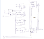
Here is my diagram without decoders - memory components connections (see attachment3).
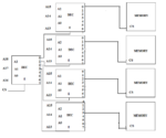
Here is my diagram with decoders - memory components connections (see attachment2).
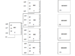
Here is an example of 128KX8 b RAM (this is Kibibit) memory using memory components 8KX8 b and decoders DEC 3/8 (see attachment1).
Here we have 16 memory components and 13 address lines for each component (because 8K can be express as the power of two - 2^13=8K ). Here, each connector of every decoder is connected to one select line of each memory component (there are total 16 connectors and 16 memory components).
In the original question, there are total 32 decoder connectors, and 4 memory components.
Question: What should be the correct diagram for the original problem (how to determine the connections), and how to determine the number of address lines of memory component when capacity is not the power of two?
Note: This is not a homework - I am practicing for exam.
32kX8 b=32000Bytes
8kX8 b=8000Bytes
Total number of memory components is n=(32KX8)/(8KX8)=4.
How to determine the number of address lines of one memory component?
In the case where the number can be represented as the power of two (2^x), x would be the number of address lines of memory component capacity (here we have 8k which is not the power of two).
Total number of decoders should be 1+4=5.
There are total 32 decoder connectors, and 4 memory components.
I don't understand how to connect connectors of decoders to memory components.
How many connections are needed and how to determine connections?
Here is my diagram without decoders - memory components connections (see attachment3).
Here is my diagram with decoders - memory components connections (see attachment2).
Here is an example of 128KX8 b RAM (this is Kibibit) memory using memory components 8KX8 b and decoders DEC 3/8 (see attachment1).
Here we have 16 memory components and 13 address lines for each component (because 8K can be express as the power of two - 2^13=8K ). Here, each connector of every decoder is connected to one select line of each memory component (there are total 16 connectors and 16 memory components).
In the original question, there are total 32 decoder connectors, and 4 memory components.
Question: What should be the correct diagram for the original problem (how to determine the connections), and how to determine the number of address lines of memory component when capacity is not the power of two?
Note: This is not a homework - I am practicing for exam.
Attachments
Last edited: