Jester
Full Member level 6
I have been asked to modify an existing PCB that is presently in production and is supposedly UL approved for use in the USA as UL 508 (Industrial control equipment)
The grounding aspect of the board jumped out at me as possibly incorrect. So if your up on ground bonding and creepage please read on and let me know if If this is not quite right or I'm simply not interpreting the rules correctly.
I'm under a NDA so I can't share every detail, however I can paint a pretty clear picture without disclosing anything confidential.
Details:
1) This device is powered from a 240V branch circuit protected with a 20A breaker
2) The device is used to distribute 120/240V with taps at each point. Much like a standard power bar, however several of these are typically cascaded to allow tapping off of power at various locations while passing the power on to the next stage.
3) The device is in a metal chassis
4) The device uses flexible metal conduit for the power in and out connections; L1, L2, Neutral and safety Ground
5) Within the metal enclosure a PCB is used to route the power (L1, L2, Neutral and Ground)
6) A simple circuit on the PCB also taps into the 120/240V via a transformer to some user accessible low voltage circuitry (I don't see this as relevant, just noted for clarity)
Now the perceived issues:
a) The pass through ground connection on the PCB is not bonded to the chassis, the ground trace is treated the same as the other live and neutral connections and is essentially floating within the constraints of the PCB.
note that the ground from module to module is continuous in that the flexible conduit is connected to the chassis (via sheet metal screws on the tab of the conduit connector), and the safety ground conductor passes through the PCB on the traces, however their is no intentional connection between these two ground paths.
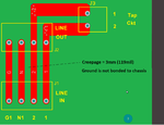
b) the creepage between the ground trace and the adjacent neutral is 3mm (119mil)
Now if the ground trace on the PCB was bonded to the chassis, I think the 3mm creepage would be fine (more than adequate), however if UL interpreted the PCB as an ungrounded device then I think the ground to neutral connection would need to be reinforced or 5mm
This is what the board looks like
The grounding aspect of the board jumped out at me as possibly incorrect. So if your up on ground bonding and creepage please read on and let me know if If this is not quite right or I'm simply not interpreting the rules correctly.
I'm under a NDA so I can't share every detail, however I can paint a pretty clear picture without disclosing anything confidential.
Details:
1) This device is powered from a 240V branch circuit protected with a 20A breaker
2) The device is used to distribute 120/240V with taps at each point. Much like a standard power bar, however several of these are typically cascaded to allow tapping off of power at various locations while passing the power on to the next stage.
3) The device is in a metal chassis
4) The device uses flexible metal conduit for the power in and out connections; L1, L2, Neutral and safety Ground
5) Within the metal enclosure a PCB is used to route the power (L1, L2, Neutral and Ground)
6) A simple circuit on the PCB also taps into the 120/240V via a transformer to some user accessible low voltage circuitry (I don't see this as relevant, just noted for clarity)
Now the perceived issues:
a) The pass through ground connection on the PCB is not bonded to the chassis, the ground trace is treated the same as the other live and neutral connections and is essentially floating within the constraints of the PCB.
note that the ground from module to module is continuous in that the flexible conduit is connected to the chassis (via sheet metal screws on the tab of the conduit connector), and the safety ground conductor passes through the PCB on the traces, however their is no intentional connection between these two ground paths.
b) the creepage between the ground trace and the adjacent neutral is 3mm (119mil)
Now if the ground trace on the PCB was bonded to the chassis, I think the 3mm creepage would be fine (more than adequate), however if UL interpreted the PCB as an ungrounded device then I think the ground to neutral connection would need to be reinforced or 5mm
This is what the board looks like