Continue to Site

Welcome to EDAboard.com

Welcome to our site! EDAboard.com is an international Electronics Discussion Forum focused on EDA software, circuits, schematics, books, theory, papers, asic, pld, 8051, DSP, Network, RF, Analog Design, PCB, Service Manuals... and a whole lot more! To participate you need to register. Registration is free. Click here to register now.

Converting voltage to resistance

Status
Not open for further replies.
> You can control the speed to some degree...
Do you think 70% and up is to much degree or maybe it works?

I'll read what you recomend me...

> ...There may be a border condition where it randomly fires
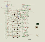
Please see the image Fig 1. Suposedly when the signal coming from 220V circuit comes to zero, wouldn't the capacitor should be discharged near enough from zero, then charge it in the oposite side? So, Isn't it sinchronic with the phase? We are attaching the optocoupler to this signal, so it should be sinchronic, or I'm wrong? Otherwise I could eliminate opto and connect as the original circuit in Fig 5, wich is one recomended here, but the first time the power stage fails, could burn everything, or What do you think about?

The problem I see is that the transistor only conduces in one way, I found in internet the arrangement in Figs 3 and 4. Would it be an option? Or finally, I could put a relay being drived by the transistor and this becomes transparently bidirectional just for a little bit more than half a pound

> Third problem, you seem to be trying to control the current through your optocoupler LED using
> transistors working from an AC supply
The optocoupler is not intended to be used as a variable resistance, but with variable signal, (if you compare Fig1 with Fig 2, you see that the selection of the transistors becomes just a digipot) so it would light when the current be enough. (maybe to add a shmitt tr.) I would have to see if the current through this resistors is enough to light it up or if it is too much. Once up, it would have to light up the triac, and the rest of half phase is a work of this last.

> you appear to limit it to only one of eight possible output steps when it is possible to have 256.
yes, I could use it as a much more resolution device but 8 steps are enough for now because I only pretend to move the power about 8%.

> if you really did want the outputs of the comparators to work the other way around, just swap the > inputs over!
Ok, thank you for the observation.

I don't know how to be more grateful to all of you, but thank you again.

Let me say that the more advanced pedagogic theories point to something named "autonomous education", wich means that the ones who knows go together with the ones learning by their own steps, instead of asignaturres and tests, and I think this is one of the more simmilar experiences to it. Thats it: you could ask for some money from government as all of you are giving a service of public interest under the most advanced pedagogic theories.

Have a good week
Sincerly
Luis J I
 

Attachments

  • OptionsPot.png
    OptionsPot.png
    115.1 KB · Views: 87

Please see the image Fig 1. Suposedly when the signal coming from 220V circuit comes to zero, wouldn't the capacitor should be discharged near enough from zero, then charge it in the oposite side? So, Isn't it sinchronic with the phase? We are attaching the optocoupler to this signal, so it should be sinchronic, or I'm wrong? Otherwise I could eliminate opto and connect as the original circuit in Fig 5, wich is one recomended here, but the first time the power stage fails, could burn everything, or What do you think about?
1. The transistor will only conduct on one half cycle and the reverse voltage on the other half cycle will damage it - not a good plan!
2. the base current turns the transistor on but to do that you have to supply a voltage between the base and emitter, feeding the base from another circuit alone will not work.
3. I don't think you understand how the opto-coupler and triac work. The opto-coupler is just an LED and phototransistor in one package, the transistor doesn't normally conduct unless the light from the LED falls on it. There is certain LED current that turns the transistor on but the MOC3021 is not intended for linear use, varying the LED current will not result in a linear change in transistor current. Even if it did, the triac would not be controlled linearly, it would do nothing then at an LED current threshold it would start to conduct all the time.

If you want to use phase control by voltage, the way to do it is to detect the zero crossing point in the AC waveform and use it to start a timer. The time period needs to be no more than one AC cycle long. (20mS for 50 Hz, 16.6mS for 60Hz). You turn the opto-coupler LED on fully when the time period has finished. If you use a short period, the triac turns on sooner and more of the cycle is passed to the motor, turn it on later and the triac starts to conduct later in the AC cycle so less power is fed to the motor. Remember that after firing a triac it stays conducting until the next zero current point then it switches itself off. You can not switch it off yourself and firing it more than once will have no effect.

So what you need is a ZCD --> voltage controlled timer --> optocoupler ---> triac ----> motor.

Note that all the control circuit is isolated from the AC lines, in your present design it isn't and you can not connect any of your logic circuits to ground or safely touch them.

Brian.
 
  • Like
Reactions: ljille

    ljille

    Points: 2
    Helpful Answer Positive Rating
Thank you very much for your comments, I admire your patience. I will take in account every one. I'll isolate control from AC circuit.

Did you see the transistor bidirectional switch circuit? In simulation only works with a 1K resistor, and when the switch terminal 1 is working as a simetrical signal + & - at a simmilar amplitude than the switched signal. That is, if the signal is 15V, is needed to on and off with 15 and -15V, but with the convenience of being not mechanical.

Just one question: Do you think that the original circuit in Fig 5 of the image OptionsPot.png works fine? (I sent it in the last post and uploaded now, but I don't see it)

I'll send you the final circuit when finished.

Thanks again and have a good day.
Luis
 

Yes, as long as the motor will accept phase control, Fig. 5 should work well, but it does require a resistance to vary the power, you can't use an optocoupler or similar component. The reason is in how it works, the resistor is not to limit the current to the triac, it is there to adjust the phase relationship between the line AC and the triac gate signal, in other words it sets the time constant of the RC network.

There is a simple but effective way you can modifiy it to give an isolated control signal, use a light dependant resistor instead of the potentiometer and shine an LED at it. You have to stop other light sources reaching the LDR but by varying the current through the LED you change the value of the resistance and hence phase shift. As a bonus, it gives you good safety isolation. The drawback is that LDRs and to some degree, LEDs do not have guaranteed parameters so if you making more than one of these circuits you might have to add some parts to make sure thay all perform identically.

Brian.
 
  • Like
Reactions: ljille

    ljille

    Points: 2
    Helpful Answer Positive Rating
I am going to ask again;
what type of induction motor you are attempting to control?

If you don't know the answer, please post TWO pictures:
-one of the complete motor
-the other, a closeup of the plate details.
 
  • Like
Reactions: ljille

    ljille

    Points: 2
    Helpful Answer Positive Rating
Schmitt the trigger

The motor has not been buyed yet. I plan to get a used universal one or simmilar. There are some used (and cheap) motors near in a garage so I will go to look for one who meet the needs, wich are: 1 h.p., 220 AC (wich is the energy available), who works with the control at about 2,400 RPMs. Even I could get one to be re-coiled. As it was commented, the ones with an ignition capacitor can't work with this while the centrifugal switch be closed, but I think that this happens in low RPMs, not at more than 2,200 RPMS (for a motor of nominal 3,600 minus the load decrement), for wich I would take the risk of seeing if this works well.

I think I could even make the arrangement with the seller so if the used motor doesn't fit my needs (while it doesn't come back burned), I could change it and get another until it works properly. If finally I don't find anything like this, wich is a low probability event, I would have to buy a new one. Although there is at 400 kms from here, I know a garage exclusively dedicated to recicle electrical motors, they have about 300 motors. It is difficult not to find something good. It is the other alternative, if I know the exact characteristics, I could ask this garage for the exact used motor to be sent to me by a logistic company as ups.

But any advice who can help me in this item, will be very appreciated.

Best Regards
Luis

- - - Updated - - -

The plan B would be to trash the previous and focus on a frequency control who works fine with this. Although I preffer to mantain it as simple as possible, so use, for instance some 555s, I have made some PIC projects, so I don't see it impossible, but I'd like to have the first prototype working already and it would take considerable time to make it.
 

Hello, here again.
Although I will post later the circuit with the digipot with basic components that I was doing, the circuit attached, wich I found in another site posted by Lazaridis, seem to solve my problem. I have a signal 0 - 5 (although I'll have to adjust it) wich feeded in the circuit (below the circuit and green in sim), would give me the firing signal in the optocoupler (blue in sim) considering the zero cross feeded into the transformer. I tryed to simulate the motor but the circuit is more complex, and the 220 V from two phases at 180 degrees, but anyway I think this will work in the circuit, because if I've got the signal in the led of the optocoupler, the system should work fine. The problem I see is that I see the pulse inverted, so, when the control signal goes up, the circuit gives me shorter flashes, (I disconnected the optocoupler and connected the led to see it and it works) and when the signal goes down, the circuit gives me a logic 1 permanent. I wonder if that would fire the triac when I would expect this only happen with sharp spikes from diac to triac. So, maybe the solution is to invert the signal who feed the led in the optocoupler, even with a TTL inverter or something. What do you think?

- - - Updated - - -

I still would have to make a conversion to the signal because the circuit will respond linearly respect the phase angle but respect power as the seno integral, so much more sensitive in the middle, indeed, the delay to power is an inverted functon, and respect speed it is not linear respect power neither, I would need the curve power to speed to know more about it. I want to move speed in the range 70 to 82% so I would fix a minimum level of voltage where speed becomes at about 70% and add voltage to the maximum I need. Maybe op amps. Some idea?
 

Attachments

  • VOLT_a_Potencia1.rar
    29.3 KB · Views: 49
  • Volt_triac.png
    Volt_triac.png
    195.1 KB · Views: 83

The way that optocoupler is driven is quite wrong and unreliable.

If you rewire it:
1. Remove R10 completely.
2. Connect pin 2 of U2 to the collector of Q3.
3. Add a new 1K resistor between U2 pin 1 and the positve supply (top of C5)
4. Re-wire the cathode of D2 to the collector of Q3
5. Add a new 1K resistor from the anode of D2 to the positive supply.

That will fix the problem of wrong optocoupler LED current and also invert the signal at the same time.

Brian.
 
  • Like
Reactions: ljille

    ljille

    Points: 2
    Helpful Answer Positive Rating
Thank you very much. I'll make the changes listed and will simulate and send the circuit back, but first I'll do some previous tasks.
 

I did the changes you sugested and then the proteus became emotional so didn't simulate under the claim of " excesive processor load", although the windows monitor doesn't goes up 22%. Then I replaced the transformator for a divisor and it worked again. I downsized 1K R10 and R13 because the led was not blinking enough and the voltage on the input of the led of moc was too low. The response can be seen on sync with the red signal (original 220V but too ugly here), diming the width of pulse, which make me think it would begin a little later than the line cicle and go making the delay, although the control band seen in simulation is stretch, so most of the cicle from 0 to 5 and back to 0 (green signal, I connected a sine generator as input to see how behave as it varies), maybe 50% of it there are not pulses at all instead of different delays, so maybe I would have to add a fixed base signal, and get a shorter range on the control signal. Maybe I'm only getting about 30 pulses each 60 pulses as the input varies 0 -5 V. Maybe I have to give the 555 another level to compare , as the original was designed for 9V.

Simulation doesn't simulate the triac although I didn't put the right equivalent motor circuit, in part cause I have not the right parameters, with wich maybe the power stage would simulate well. Anyway if the control stage works, I suppose the power stage will go well.
Do you think I could have success with this circuit?
 

Attachments

  • VOLT_a_Potencia4a.rar
    24.1 KB · Views: 47
  • With_newR.png
    With_newR.png
    142.6 KB · Views: 65

It wont work with that schematic. Please follow the instructions I gave in post #28 and try again.

Brian.
 
  • Like
Reactions: ljille

    ljille

    Points: 2
    Helpful Answer Positive Rating
Excuse me, I've got confused, I'm sending the right squematic. Certainly the voltages in the moc are now right.

- - - Updated - - -

I suppose you can see the simulation, it looks right.
 

Attachments

  • VOLT_a_Potencia5.rar
    27.7 KB · Views: 44
  • Corrected.png
    Corrected.png
    17.1 KB · Views: 66

That is correct.
I do not use Proteus/ISIS so I can't see your simulation results but based on what you say, it seems the problem is now solved.

Brian.
 
  • Like
Reactions: ljille

    ljille

    Points: 2
    Helpful Answer Positive Rating
As I told previously, and trying to be grateful I want to share the idea of a digipot who could be used in different scenarios, adjusting input and output to different ranges.

It selects a digit and close a relay, just one, depending on voltage input. (I shared the bidir-switch with transistors but it only works on some circumstances) The way of selecting resistors on input and output could be used to linearize or maybe on the oposite, to give a logaritmic output, but as it is now can be used as a digipot, as it gives a variable resistance proportional to its input and to the resistors at output, without serial conversions.

Isolation and power depends on the selected relays.

In this configuration is a resistor divider with same value resistors of 5.7K, feeded with 12 V, giving an output between 0-335 mV, not linear, as correspond to a divider, (about 0,110,125,140, 135, 165, 225, 335 mV), but it instead could handle different circuits each one. It can grow on steps or be shrinked. Yes it is a pour resolution, but it has some other advantages.

The leds are just to see it better, but can be omitted. I was told the cmos buffers can be replaced just inverting the feeding voltage to comparators. anyway they are just two chips.

The circuit is about 15 dlls so it can be affordable for many and may be useful to somebody.

For instance and just dreaming as an alcoholic mind (I don't drink it), if the temp. would be someway fixed and pressure would be the proportional input, it could handle the valves for different distillation stages.

If somebody has a simmilar functionality but with a better circuit and want to share it, it is welcome.

Thanks Brian for all your attentions. Thank you to other who gave me your time. I will make the previous circuit phisically and then will tell you how it worked, in about one week I'll have it. (A friend of mine with some little help from me have finished a cnc drilling machine to make the circuits and we will use it to do it just after we deal with a little of backslash and few losen steps)

If there is another way to help, please tell me.

Sincerly
Luis J. I.

I hope you some day get proteus so you could see same simulations, but the fact you don't have it makes me think that you have something better, what is it?

Is there something like a "circuits bank"?

- - - Updated - - -

I was forgetting to send the graph of response of the corrected circuit in the input of the moc. It is here.

- - - Updated - - -

Correcting: The input has a 4.2 V as offset and a variation of 0.75 mV. is there a way to make shorter the offset and bigger the real input or at least increase this last? (Volt_a_pot4b.png)
 

Attachments

  • Digipot1B_response.png
    Digipot1B_response.png
    396 KB · Views: 73
  • Digipot1B.rar
    35.2 KB · Views: 47
  • Digipot1A.png
    Digipot1A.png
    164.6 KB · Views: 69
  • Volt_to_power.png
    Volt_to_power.png
    138.2 KB · Views: 63
  • Volt_a_Pot4b.png
    Volt_a_Pot4b.png
    32.8 KB · Views: 60

To select one of several wires based on incoming voltage, sounds like a job for a 3914 IC (1-of-10 dot/bargraph driver).
The IC contains a stack of window comparators very much like your image #3.
It has 10 outputs, each of which could drive a transistor to energize a relay, as shown in your image #3.
 

The LM3914 (or LM3915 for a log response) is an excellent idea and saves you lots of components. If the relays are small enough (signal relays) they may be able to drive them directly without the transistors. I am still concerned about the whole idea of switching resistors like this though and where the 'switched resistance' fits into the bigger picture, especially as the resistors are connected to the same supply as the remaining circuit, indicating no isolation.

If you really want to use this method, you could consider using a simple MCU, something like the PIC16 series which has an ADC built in and can easily drive 8 relays. It would use fewest components and allow you to decide the voltage to resistance curve yourself. A little rewiring of the relays and different resistor values in the chain would allow better control of the resistance value.

I hope you some day get proteus so you could see same simulations, but the fact you don't have it makes me think that you have something better, what is it?
I don't use Windows and Proteus only runs under Windows. LTSpice IV runs fine under Linux so I use that when necessary.

Brian.
 

Status
Not open for further replies.

Part and Inventory Search

Welcome to EDABoard.com

Sponsor

Back
Top