neazoi
Advanced Member level 6
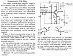
Hi, attached is a single transistor AF CW filter. I am not sure:
1. Why the peaking pot and R2 pot is used instead of a single pot. Is it just for "fine tuning"?
2. How are the feedback potentiometers connected and adjusted? Are they a stereo potentiometer ot two separate 10K ones? Also are their tapers connected together AND with the end points of their resistive elements (there is no connection DOT there)?
3. Also, where is the transistor DC ground?Is there a typo error?
4. Does R1 have to be logarithmic?
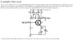
Maybe another similar PNP circuit I attach, can help to spot the errors...
Oh, btw, if someone has the Radio amateurs handbook from 1970, I would love to have a scan or a photo of the pages the circuit is described in.
1. Why the peaking pot and R2 pot is used instead of a single pot. Is it just for "fine tuning"?
2. How are the feedback potentiometers connected and adjusted? Are they a stereo potentiometer ot two separate 10K ones? Also are their tapers connected together AND with the end points of their resistive elements (there is no connection DOT there)?
3. Also, where is the transistor DC ground?Is there a typo error?
4. Does R1 have to be logarithmic?
Maybe another similar PNP circuit I attach, can help to spot the errors...
Oh, btw, if someone has the Radio amateurs handbook from 1970, I would love to have a scan or a photo of the pages the circuit is described in.
Attachments
Last edited: