Continue to Site

Welcome to EDAboard.com

Welcome to our site! EDAboard.com is an international Electronics Discussion Forum focused on EDA software, circuits, schematics, books, theory, papers, asic, pld, 8051, DSP, Network, RF, Analog Design, PCB, Service Manuals... and a whole lot more! To participate you need to register. Registration is free. Click here to register now.

Seeking advice regarding structure of a DC-DC/PWM reg. for personal vaporizer.

Status
Not open for further replies.
Or is that creating a ground loop or might it cause some other ill effect?
... ... ...
I know such routing is not good but could it be just "OK" without inducing a lot of noise given the low current amplitude, does anyone have any thoughts/opinions about that?

I have not fully understood but I do not see any ground loop yet; ground loops are problem with high current circuits but in your case the high current path is not likely to be noise-sensitive.

Which part of the routing you think is not good?
 

I have made two pictures to clearly illustrate the situation, but first I'd like to address another aspect(my attention isn't enough for both right now).

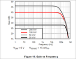
I am hoping to be able to use a INA225 current sense amplifier, it has selectable gain and here is some specs and a picture over gain vs freq:
25V/V - gain error(±0.15%V), bandwidth(250kHz)
50V/V - gain error(±0.15%V), bandwidth(200kHz)
100V/V - gain error(±0.2%V), bandwidth(125kHz)
200V/V - gain error(±0.3%V), bandwidth(70kHz)
all 4 settings have the same offset voltage of ±150µV.
ina225_freq_vs_gain.png

But the amount of gain isn't the only parameter related to bandwidth is it?
If I judge the bandwidth solely on the gain then it looks like I will be just fine for may application if used with ether of 25V-, 50V- or 100V/V.
But one thing that I am worried about is the information gained from such a current measurement, I would be surprised if the signal from a INA225 sensing the current right after the inductor could be used for peak-current control, I'm not sure but I have gotten the idea that if you measure the current before the inductor you get the peak-current information while if you measure the current after the inductor then you can get the average-current information.

But if that would be true then why measure the average current, shouldn't I be able to measure the peak-current value and then calculate the average current?
The more troubling aspect is this, how many sample points do I need to collect through each switching period in order to be sure about the peak-current amplitude?
And is a INA225 even capable of supplying the voltage representing the peak-current waveform... it is analog after all so I would hope it could.

I'd be very interested in anyone's thoughts about these aspects of measuring the current in a way that allows the information to be used for peak-current control.

Another option would be to use a fixed gain current sense amplifier with a bandwidth of 400kHz.

- - - Updated - - -

TI has added a very neat error calculator for current sense amplifiers tailored to each specific amplifier on the right side of there information page(about specific amplifiers), this is a link for the INA225 page.
 

If "peak current control" refers to current mode pwm controller operation, the current sense bandwidth requirement depends strongly on the pwm frequency. The current into the "left" terminal of the inductor is however the same as what comes out of the "right terminal, according to elementary electric network rules, the same triangle waveform.

As far as I remember previous discussions, CSD95472 is equipped with a current monitor output, you won't need a separate shunt and current sense amplifier for peak current control.
 

Yes current mode pwm controller operation is what I meant(the frequency is 100kHz)

I am somewhat torn about what to do, since there is pretty much no information about the current sense circuit in the CSD95472, all I know is that I can chose a reference voltage and feed that to a pin on the CSD95472 and then read a voltage from a output pin representing the current through the IC.

So I have planned not to use that feature and include another current measuring circuit, but I do still have a hope that I will be able to make measurements and figure out that current sensing enough to be able to use it.
But my thoughts are usually too fuzzy to allow me to know whether or not that hope is viable.

But if I imagine what I would do to find out if I can use that ICs internal current sensing then maybe I would find out if I need another current sensing or not.

I had planned to tie the CSD95472's reference voltage pin to a 12-bit onboard(mcu) DAC so that I can adjust the reference voltage, but perhaps I would do better by simply feeding the CSD95472 the same reference voltage as I will be using for the ADC. That sounds as it makes sense.

Then it would be a matter of controlling the current(or externally measure the current into the converter) while I monitor the current sense output pin's voltage and correlate those 2 measurements.

But I am not sure such a procedure would be sufficient, but when i read about other such sensing techniques and they write in documents that 4% accuracy is a great accuracy then I start to wonder about what is sufficient and what is not.

My external current sensing would according to TI's graphical presentation of current sense amplifiers accuracy according to my operating parameters be about 0,2% until the current gets down below 15A when the accuracy starts to get much worse, at single digit current amplitudes it gets up to around 5% and then a below 1A, 0,1A for example(this is the lowest end of the measuring range in this case) the accuracy is displayed as being 16%.
But I would never need to measure anything below 5A and it is probable that it is rare for me to measure below 15A.

Does anyone know what sort of accuracy one could expect from a lossless current sensing using a resistor and capacitor in parallel to the inductor(possibly a couple of more resistors in series with the sense tracks as well as one resistor placed across the sense tracks, which would be to adjust the response or some aspect of the current sensing which I can't recall what it was right now) with a DMOS type of IC?

Because if the accuracy of the current sensing using the CSD95472 is as low as >2% then I would start wondering about the performance of the control loop comparing having access to current measurements with 0,2% accuracy/error and access to current measurements with 2% accuracy/error.

The goal of this design is to implement a wattage or temperature regulation as accurate as I can and especially in case of the wattage regulation I would think that 0,2% vs 2% accuracy would make a big deal of difference, I need to sleep now but unless someone here knows or thinks something about the great unknown hiding inside CSD95472 then I guess I will start looking at similar IC's from other manufacturers tomorrow in order to see what sort of accuracy there current sensing is achieving. Or I will do that regardless.
 

I am often wrong but I think you have lots of confusion. I mention a few points:

1. Most common current measurements end up measuring voltage; using a current sensing resistor is the simplest I-to-V converter. The accuracy is expected to be linear in nature.

2. When you are measuring a current that changes in time (who wants to measure a constant current?) you need to bother about the time taken to "read" the voltage. If you use a high pass filter (place a capacitor in parallel with the resistor), you need not bother about the time it takes to read the voltage.

3. Using a current sense resistor to measure current is not really "lossless".

4. You need to have a "model" before you consider wattage or temperature regulation; but you will, sooner or later, come back to the current sense...
 

Status
Not open for further replies.

Part and Inventory Search

Welcome to EDABoard.com

Sponsor

Back
Top