Continue to Site

Welcome to EDAboard.com

Welcome to our site! EDAboard.com is an international Electronics Discussion Forum focused on EDA software, circuits, schematics, books, theory, papers, asic, pld, 8051, DSP, Network, RF, Analog Design, PCB, Service Manuals... and a whole lot more! To participate you need to register. Registration is free. Click here to register now.

How to check CAN line weakness

Status
Not open for further replies.

jtronix

Member level 3
Joined
Dec 4, 2012
Messages
67
Helped
0
Reputation
0
Reaction score
0
Trophy points
1,286
Activity points
1,860
How to check CAN line ??

Hello,

How to check CAN communication line weakness??

In my system my one device is communicate to several controllers via CAN communication. suddenly one of my CAN device is stop responding and does not communicate with master CAN controller.

For verification purpose i have connect my master controller to other system where i got the same issue.

After searching on internet i found that in CAN communication weak signal causes the issue. May few device will communicate and some of may not.

Can anybody know how to test CAN line??
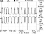
 

Re: How to check CAN line ??

waveform is attached for reference.


Please answer someone
 

Attachments

  • F0000TEK.jpg
    F0000TEK.jpg
    38.8 KB · Views: 67

For verification purpose i have connect my master controller to other system where i got the same issue.
So you suspect the master controller is sending weak signal.

In the CAN network most of the signal current pass through the bus termination resistors. So if you increase the value of the termination resistors then the signal voltage level will increase and the system may work.
Usually termination resistors are 120 ohms. Try with 180 ohms. Due to increased termination resistance, reflection related problem will increase but may not too much. See what happens.
 

You are making a rookie mistake when viewing the CAN waveforms on a scope.

The grounds (arrows 1 and 2) should both be aligned.
CANH will automatically sit on the top, and CANL on the bottom.

Then, and only then will you see if you meet the CANBus voltage requirements for recessive and dominant states. Which include not only min and max voltage values, but the differential values too.
Google CANBus for the valid voltage value range.

Use the automatic measurements correctly too.........Use Ch1 max, Ch1 min, Ch2 max and Ch2 min. Remove any RMS measurements....those are meaningless.
 

Status
Not open for further replies.

Similar threads

Part and Inventory Search

Welcome to EDABoard.com

Sponsor

Back
Top