Continue to Site

Welcome to EDAboard.com

Welcome to our site! EDAboard.com is an international Electronics Discussion Forum focused on EDA software, circuits, schematics, books, theory, papers, asic, pld, 8051, DSP, Network, RF, Analog Design, PCB, Service Manuals... and a whole lot more! To participate you need to register. Registration is free. Click here to register now.

[SOLVED] Automatic Battery Charger Help Needed

Status
Not open for further replies.
I think 80 MHz Fosc is not generating and I can't test it because my Rigol Oscope is limited to 50 MHz.
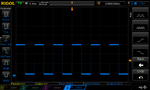
The statement makes no sense. Fosc isn't output to a pin, you can only measure it indirectly anyway.
 

Now if oscillator configuration is correct then why I am not getting 100 KHz pwm ?
 

I checked the code you posted yesterday, it doesn't set OSCCON or PLLFBD anywhere.
 

    V

    Points: 2
    Helpful Answer Positive Rating
Here is the code which includes Oscillator configurations. I am using this code only. Oscillator configuration was done today. If anybody needs the complete mikroC PRO dsPIC project then I will post that too.


Code C - [expand]
1
2
3
4
5
6
7
8
9
10
11
12
13
14
15
16
17
18
19
20
21
22
23
24
25
26
27
28
29
30
31
32
33
34
35
36
37
38
39
40
41
42
43
44
45
46
47
48
49
50
51
52
53
54
55
56
57
58
59
60
61
62
63
64
65
66
67
68
69
70
71
72
73
74
75
76
77
78
79
80
81
82
83
84
85
86
87
88
89
90
91
92
93
94
95
96
97
98
99
100
101
102
103
104
105
106
107
108
109
110
111
112
113
114
115
116
117
118
119
120
121
122
123
124
125
126
127
128
129
130
131
132
133
134
135
136
137
// LCD module connections
sbit LCD_RS at LATB4_bit;
sbit LCD_EN at LATB5_bit;
sbit LCD_D4 at LATB6_bit;
sbit LCD_D5 at LATA0_bit;
sbit LCD_D6 at LATA1_bit;
sbit LCD_D7 at LATA4_bit;
 
sbit LCD_RS_Direction at TRISB4_bit;
sbit LCD_EN_Direction at TRISB5_bit;
sbit LCD_D4_Direction at TRISB6_bit;
sbit LCD_D5_Direction at TRISA0_bit;
sbit LCD_D6_Direction at TRISA1_bit;
sbit LCD_D7_Direction at TRISA4_bit;
// End LCD module connections
 
sbit Shutdown at LATB9_bit;
 
unsigned char msg[23], i = 0;
unsigned char myFlags = 0;
unsigned char charger_state_counter = 0;
double pwm_duty_base_value = 783;
double raw_adc_value[3] = {0.0, 0.0, 0.0}, previous_raw_adc_value[3] = {40.0, 40.0, 10.0};
unsigned int pwm_duty = 0, previous_pwm_duty = 786;
unsigned int trickle_charge_delay_counter = 0;
unsigned char trickle_charge_state_counter = 0;
double input_voltage = 0.0, previous_input_voltage = 40.0, battery_voltage = 0.0, previous_battery_voltage = 20.0, battery_current = 0.0;
 
unsigned int j = 0;
 
const code char msg1[] = "   Battery Charger  ";
const code char msg2[] = "Mode: ";
const code char msg3[] = "Input   V: ";
const code char msg4[] = "Battery V: ";
const code char msg5[] = "Battery I: ";
const code char msg6[] = "Trickle ";
const code char msg7[] = "Boost ";
const code char msg8[] = "6V ";
const code char msg9[] = "12V";
 
char *CopyConst2Ram(char *dest, const code char *src) {
    char *d;
 
    d = dest;
 
    for(;*dest++ = *src++;)asm clrwdt;
 
    return d;
}
 
void main() {
 
     asm clrwdt
     OSCCON = 0b0011001110100000;
     CLKDIV = 0b0000000000000000;
     PLLFBD = 0b0000000000100110;
     ACLKCON = 0b0010111110000000;
     OSCTUN = 0x00;
     
     ADPCFG = 0xFFE3;
              
     TRISA = 0xFFE0;
     TRISB = 0xFF8F;
         
     PORTA = 0x00;
     PORTB = 0x00;
          
     LATA = 0x00;
     LATB = 0x00;
         
     Delay_ms(180);
     
     Lcd_Init();
     Lcd_Cmd(_LCD_CURSOR_OFF);
     Lcd_Cmd(_LCD_CLEAR);
     
     Lcd_Out(1,1,CopyConst2Ram(msg, msg1));
     asm clrwdt
     Delay_ms(1000);
     asm clrwdt
     Delay_ms(1000);
     asm clrwdt
 
     LCD_Cmd(_LCD_CLEAR);
     
     Lcd_Out(1,1,CopyConst2Ram(msg, msg2));
     Lcd_Out(2,1,CopyConst2Ram(msg, msg3));
     asm clrwdt
     Lcd_Out(3,1,CopyConst2Ram(msg, msg4));
     Lcd_Out(4,1,CopyConst2Ram(msg, msg5));
 
     asm clrwdt
     
     Shutdown = 0;
     
 
     pwm_duty = PWM1_Mc_Init(100000,1, 1, 0);
     PWM1_Mc_Set_Duty(399, 1);
     PWM1_Mc_Start();
 
     /*
     pwm_duty = PWM_Init(100000, 1, 1, 2);
     PWM_Set_Duty(399, 1);
     PWM_Start(1);
     */
     
     TRISB = 0x000F;
     
     ADC1_Init();
     
     while(1) {
     
            asm clrwdt
 
            //read input voltage, battery voltage and battery current in a loop
            for(i = 0; i < 3; i++) {
                raw_adc_value[i] = 0;
                
                for(j = 0; j < 128; j++) {
                     raw_adc_value[i] += (double)ADC1_Read(i + 2);
                     Delay_ms(1);
                }
                
                raw_adc_value[i] /= 128.0;
            }
 
            //convert raw adc value to actual input voltage
            input_voltage = raw_adc_value[0] * 37.910298 / 1023.0;
 
            //convert input voltage to string
            sprintf(msg, "%4.1f", input_voltage);
            LTrim(msg);
            strcat(msg, "V  ");
            //display input voltage on Lcd
            Lcd_Out(2,12,msg);
     }
}


This is the new code but still getting only 34.2 KHz. I think the sequence of oscillator switching is correct. What do you people say ?


Code C - [expand]
1
2
3
4
5
6
7
8
void main() {
 
     asm clrwdt
 
     CLKDIV = 0b0000000000000000;
     PLLFBD = 0b0000000000100110;
     OSCCON = 0b0000001100000001;
     OSCTUN = 0x00;


Edit: Picture shows my new settings.
 

Attachments

  • Osc Config 2.png
    Osc Config 2.png
    37.2 KB · Views: 66
Last edited:

This is for dsPIC33 and PIC24

https://microchip.wikidot.com/16bit:osc-pll-80mhzpll

He is changing Osc from FRC to XT. He has used config settings for that but in mikroC PRO dsPIC I don't have access to config registers. How to implement it ?

- - - Updated - - -

Edit:

This is the new code. See attached picture for project settings. I am still getting only 34.2 KHz PWM. is it a bug of mikroC PWM library ?


Code C - [expand]
1
2
3
4
5
6
7
8
9
10
11
12
13
14
15
16
17
18
19
20
21
22
23
24
25
26
27
28
29
30
31
32
33
34
35
36
37
38
void main() {
 
     asm clrwdt
 
     //Default values at POR
     //Fref = 0.5 * 8 MHz = 4 MHz
     //Fvco = 50/2 * Fin = 100 MHz  //N1 = 2, M = 50
     //Fosc = (50 * Fin)/(2 * 4) = 25 MHz (N1 = 2, N2 = 4, M = 50)
     
     //Oscillator settings to be changed to
     //Fref = 0.5 * 8 MHz = 4 MHz
     //Fvco = 40/2 * 8 MHz = 160 MHz //N1 = 2, M = 40
     //Fosc = (Fin * M)/(N1 * N2) = (8 MHz * 40)/(2 * 2) MHz  = 80 MHz (N1 = 2, N2 = 2, M = 40)
 
     //Start of Oscillator Configuration
     
     PLLFBD = 38; //M = 40
     
     CLKDIV.PLLPOST_0 = 0;   //N1 = 2
     CLKDIV.PLLPOST_1 = 0;
     
     CLKDIV.PLLPRE_0 = 0;    //N2 = 2
     CLKDIV.PLLPRE_1 = 0;
     CLKDIV.PLLPRE_2 = 0;
     CLKDIV.PLLPRE_3 = 0;
     CLKDIV.PLLPRE_4 = 0;
     
     NOSCG_0_bit = 1;
     NOSCG_1_bit = 1;
     NOSCG_2_bit = 0;
     
     OSWEN_bit = 1;
     
     while((OSCCON & 0b0111000000000000) != 0b0011000000000000);
     
     while(LOCK_bit != 1);
 
     //End of Oscillator Configuration


Attachments

  • Osc Config 3.png
    Osc Config 3.png
    36.7 KB · Views: 65

Ok. 99% problem is solved.

Now, I tried PPS and PWM library and got stable 100 KHz PWM. This means the Oscillator configuration was correct. The problem is in PWM Motor Control Library of mikroC PRO dsPIC which is generating incorrect PWM frequency.

Here is the new code. See attached image which shows the signal. See also Osc settings.


Code C - [expand]
1
2
3
4
5
6
7
8
9
10
11
12
13
14
15
16
17
18
19
20
21
22
23
24
25
26
27
28
29
30
31
32
33
34
35
36
37
38
39
40
41
42
43
44
45
46
47
48
49
50
51
52
53
54
55
56
57
58
59
60
61
62
63
64
65
66
67
68
69
70
71
72
73
74
75
76
77
78
79
80
81
82
83
84
85
86
87
88
89
90
91
92
93
94
void main() {
 
    asm clrwdt
 
    //Default values at POR
    //Fref = 0.5 * 8 MHz = 4 MHz
    //Fvco = 50/2 * Fin = 100 MHz  //N1 = 2
    //Fosc = (50 * Fin)/(2 * 4) = 25 MHz (N1 = 2, N2 = 4, M = 50)
 
    //Oscillator settings to be changed to
    //Fref = 0.5 * 8 MHz = 4 MHz
    //Fvco = 40/2 * 8 MHz = 160 MHz
    //Fosc = (Fin * M)/(N1 * N2) = (8 MHz * 40)/(2 * 2) MHz  = 80 MHz (N1 = 2, N2 = 4, M = 40)
 
    //Start of Oscillator Configuration
 
    //CLKLOCK_bit = 0;
 
    PLLFBD = 38; //M = 40
 
    CLKDIV.PLLPOST_0 = 0;   //N1 = 2
    CLKDIV.PLLPOST_1 = 0;
 
    CLKDIV.PLLPRE_0 = 0;    //N2 = 2
    CLKDIV.PLLPRE_1 = 0;
    CLKDIV.PLLPRE_2 = 0;
    CLKDIV.PLLPRE_3 = 0;
    CLKDIV.PLLPRE_4 = 0;
 
    NOSCG_0_bit = 1;
    NOSCG_1_bit = 1;
    NOSCG_2_bit = 0;
 
    OSWEN_bit = 1;
 
    while((OSCCON & 0b0111000000000000) != 0b0011000000000000);
 
    while(LOCK_bit != 1);
 
    //End of Oscillator Configuration
 
    ADPCFG = 0xFFE3;
 
    TRISA = 0xFFE0;
    TRISB = 0xFF8F;
 
    PORTA = 0x00;
    PORTB = 0x00;
 
    LATA = 0x00;
    LATB = 0x00;
 
    Delay_ms(180);
 
    Lcd_Init();
    Lcd_Cmd(_LCD_CURSOR_OFF);
    Lcd_Cmd(_LCD_CLEAR);
 
    Lcd_Out(1,1,CopyConst2Ram(msg, msg1));
    asm clrwdt
    Delay_ms(1000);
    asm clrwdt
    Delay_ms(1000);
    asm clrwdt
 
    LCD_Cmd(_LCD_CLEAR);
 
    Lcd_Out(1,1,CopyConst2Ram(msg, msg2));
    Lcd_Out(2,1,CopyConst2Ram(msg, msg3));
    asm clrwdt
    Lcd_Out(3,1,CopyConst2Ram(msg, msg4));
    Lcd_Out(4,1,CopyConst2Ram(msg, msg5));
 
    asm clrwdt
 
    Shutdown = 0;
 
    pwm_duty = PWM1_Mc_Init(100000,1,1,3);
    PWM1_Mc_Set_Duty(399, 1);
    PWM1_Mc_Start();
 
    TRISB = 0x000F;
    
    Unlock_IOLOCK();
    PPS_Mapping_NoLock(11, _OUTPUT, _OC1);
    Lock_IOLOCK();
 
    pwm_duty = PWM_Init(100000, 1, 1, 2);
    PWM_Set_Duty(pwm_duty/2, 1);
    PWM_Start(1);
 
    ADC1_Init();
     
    while(1) {


Attachments

  • DS1Z_QuickPrint24.png
    DS1Z_QuickPrint24.png
    35.6 KB · Views: 76
  • osc config 5.png
    osc config 5.png
    36.1 KB · Views: 65

Status
Not open for further replies.

Similar threads

Part and Inventory Search

Welcome to EDABoard.com

Sponsor

Back
Top