Continue to Site

Welcome to EDAboard.com

Welcome to our site! EDAboard.com is an international Electronics Discussion Forum focused on EDA software, circuits, schematics, books, theory, papers, asic, pld, 8051, DSP, Network, RF, Analog Design, PCB, Service Manuals... and a whole lot more! To participate you need to register. Registration is free. Click here to register now.

[General] Noise in AC voltage measurement

Status
Not open for further replies.

archusvijay1

Member level 3
Joined
Mar 12, 2014
Messages
61
Helped
0
Reputation
0
Reaction score
0
Trophy points
6
Activity points
553
Hi,

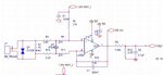
I am trying to measure AC rms voltage using PIC microcontroller. I have attached the circuit for measurement. I am connecting a 3V step down transformer out to the input of the circuit.The feedback capacitor has been added to reduce the noise, but I am getting noise if I add this. This is getting smooth after the low pass filtering. Everything else, like clamping the voltage and all are properly happening. Do I really need to place the feedback capacitor? What are the recommended values if it is needed?

Thanks
 

Attachments

  • image.JPG
    image.JPG
    44.4 KB · Views: 76

Hi,

I assume you modified the original circuit...
and now there are some problematic modifications.
according
* bias voltage
* common mode input voltage
* input impedance
* input votage range
* output voltage range
* frequency

****
First of all: You could do completely without OPAMP.

Like this.
ct1.png

***
I see you really want to calculate RMS. This is good. Especially when the waveform differs from sine shape.
On the other hand you attenuate the frequencies above 50Hz... so you get an almost sine shape.
Is this what you want?

Klaus
 

On the other hand you attenuate the frequencies above 50Hz... so you get an almost sine shape.
Is this what you want?
Yes. This is what we want. It is going to be used in a high noise scenario, like old inverters. What I am asking is the capacitor C7 is creating noise in the circuit. Is it recommended to remove that capacitor? everything else is working fine.

thanks
 

Hi,

C7 is not creating the noise. But it may cause to amplify it.

I assume it is common mode noise. Usually a difference amplifier attenuates common mode noise.
But only if R1 value = R15 value, which isn't the case here (here I assume someone didn't understand the circuit, but modifed it).
Adding C7 to R15 makes this even worse.

In your case you may disconnect C7. To further reduce common mode noise I recommend to use two 100nF capacitors.
Connect them at each side of C4 to GND.

Because this adds another 50nF to C4 and fc is close to mains frequency you may expect up to 10% less output voltage.
If you don't want this you may use 10nF capacitors

****
By far the better solution is to correct the wrong R1 and R15 values. This brings improvement in almost any function of the circuit: noise, common mode input voltage range, symmetry, differential input voltage range...

Klaus
 

Hi, thanks for the quick and valuable reply. I'll change the resistors and update the result.
 

Hi,
Noise has reduced to a greater extent. I could measure the RMS value with our laboratory setup. I assume there will be much more noise when it is installed in the field. So I should eliminate as much noise I can with this. How to select C1 and C7 values to further reduce noise? Shall I use 100nF in both places?
 

Hi,

Please give the complete new circuit.

Generally.
C7 with R15 act as a low pass filter.
The same values you need to install at R1 and a new C. ( R1 = R15, new C = C7).

Fc = 1 / ( 2 × Pi × R × C) .... as usual.

Klaus
 

Status
Not open for further replies.

Similar threads

Part and Inventory Search

Welcome to EDABoard.com

Sponsor

Back
Top