vieha007Electronic
Junior Member level 3
- Joined
- Feb 27, 2011
- Messages
- 25
- Helped
- 3
- Reputation
- 6
- Reaction score
- 1
- Trophy points
- 1,283
- Location
- South Korea
- Activity points
- 1,559
hi all,
As I know, there are 3 types of CMOS comparators:
1. Opamp-based (low speed)
2. Latch-based (high speed but also this type is discrete-time comparator and need clock signal for tracking and latching phases).
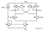
3. Hysteresis type (as shown in the attached figure below)
Currently, I am designing comparator used in buck converter. However, I can not explain in details about 2 things below:
1. The mechanism of this circuit, especially, the "positive feedback" mechanism in this circuit.
2. The small signal to analyze and calculate the propagation delay time
(The analysis for opamp-based and latch-based are deeply analyzed in Allen and Martin's book, however, I can not find down some material for the hysteresis comparator using cross-gate)
Do you have any opinions about this. Always appreciate the supports from community.
Thank you
