Continue to Site

Welcome to EDAboard.com

Welcome to our site! EDAboard.com is an international Electronics Discussion Forum focused on EDA software, circuits, schematics, books, theory, papers, asic, pld, 8051, DSP, Network, RF, Analog Design, PCB, Service Manuals... and a whole lot more! To participate you need to register. Registration is free. Click here to register now.

Ultra simple mosfet voltmeter schematic

Status
Not open for further replies.

neazoi

Advanced Member level 6
Joined
Jan 5, 2008
Messages
4,119
Helped
13
Reputation
26
Reaction score
15
Trophy points
1,318
Location
Greece
Activity points
36,918
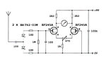
Hi I would like to build a very simple mosfet voltmeter. Mosfet, so that it does not load the measuring circuit. It will use an analogue meter.
Can I use the 2n7000 to build this https://www.youtube.com/watch?v=YkZuBu-EUhc ???
What if I want to also measure negative voltage as well? Shall I just connect the ground to the gate and the negative voltage to the source, will that be ok?
 
Last edited:

Look at FET Id=f(Vgs) curve and see if it's of any use for your purposes. The idea of using a calibration series resistor raises doubts about the author's analog design skills. Might be copy-and-past error while modifying an original common drain circuit.
 
  • Like
Reactions: neazoi

    neazoi

    Points: 2
    Helpful Answer Positive Rating
Look at FET Id=f(Vgs) curve and see if it's of any use for your purposes. The idea of using a calibration series resistor raises doubts about the author's analog design skills. Might be copy-and-past error while modifying an original common drain circuit.

I know I said mosfet, but this seems ok http://www.simplecircuitdiagram.com/2010/01/25/fetvm-fet-voltmeter/ plus it can measure negative voltages as well. Any new replacement for the old 2n4340? They use is because of it's low noise low leakage, but it's quite expensive.
Maibe a better option would be this http://www.next.gr/meter-counter/voltmeters/fet-voltmeter-l13908.html since the FETs are matched?
 

Differential FET amplifier with resistive degeneration (the 500 ohm variable resistor) is a different topic and has nothing in common with the post #1 circuit. If you omit the diode, the output can be bipolar, no need to flip the input wires.
 

Differential FET amplifier with resistive degeneration (the 500 ohm variable resistor) is a different topic and has nothing in common with the post #1 circuit. If you omit the diode, the output can be bipolar, no need to flip the input wires.

You mean something like this?
(but by including a series 1M with the gate and removing the input circuit up to the 100pf)
 

Attachments

  • field_strength_meter_balanced_FET.jpg
    field_strength_meter_balanced_FET.jpg
    37.9 KB · Views: 117

Status
Not open for further replies.

Similar threads

Part and Inventory Search

Welcome to EDABoard.com

Sponsor

Back
Top