Continue to Site

Welcome to EDAboard.com

Welcome to our site! EDAboard.com is an international Electronics Discussion Forum focused on EDA software, circuits, schematics, books, theory, papers, asic, pld, 8051, DSP, Network, RF, Analog Design, PCB, Service Manuals... and a whole lot more! To participate you need to register. Registration is free. Click here to register now.

high side gate driver ground and igbt emitter

Status
Not open for further replies.

deniz88

Member level 2
Joined
Jul 28, 2009
Messages
47
Helped
0
Reputation
0
Reaction score
0
Trophy points
1,286
Location
germany
Activity points
1,703
Hi ,

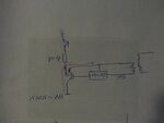
at the high side gate driver, we connect ground of the driver with the emitter of the IGBT.
when the IGBT turned on, on the emitter there will be tousends volt and tousends volt will be connected to the ground of the high side driver.
what i am missing? why it doesn't break the driver circuit?
thanks a lot.

best regards.
 

Hi,

High side drivers are made for this high voltage. Read the datasheet.
...
There are tiny Mosfets carrying a huge of hundreds of amperes...why don't they get killed? --> They are made for the high current.

What else can we say?

Klaus
 

hi Klaus,
thanks for your answer,

i am doing gate driver myself, there are many opamps, ADCs,...
when their ground gets high voltage from Emitter of the IGBT, how it doesnt damage the circuit?

so power supply of the driver is 15V and ground is tousends of volts... shouldnt components get destroyed?
 

Hi,

First: you are wrong: on a high side driver, maybe it has 15V power supply. The power supply is referenced to a GND pin, then this pin is not the emitter ppin of the IGBT.

Again: look at the datasheet.

*******

Second you are wrong: in a typical high side driver ther is neither an Opamp, nor an ADC.

Again: look at the datasheet.

*******
I don't recommend you to build you own high side driver, because you don't have the electronical knowledge and it seems you don't have the knowledge about safety rules for high voltage. Don't hurt/kill yourself and don't hurt/kill others.

If you want to build a high side driver on your own you
* either use a proven schematic concept,
* or you need to develop a schematic concept of your own.
In both cases you should show us the schematic to discuss the details of the circuit.

Talking about wrong assumptions is useless.

Klaus
 

IGBT drivers must implement galvanic isolation between driver logic and IGBT, at least for the high side. In industrial IGBT circuits, driver modules with magnetic isolation that also include an isolated DC/DC converter are popular.
 

thank you for the answers
IGBT drivers must implement galvanic isolation between driver logic and IGBT
i was wondering, why it is fine, when there is galvanic isolation, because on the high side driver, Vc = 15V, ground is with high voltage connected when the igbt turns on?
 

Hi,

IGBT drivers must implement galvanic isolation between driver logic and IGBT, at least for the high side.

The OP doesn´t say to wich device he refers....
But when I look into IR2110 or IR2130 datasheet (both say they can be used as IGBT driver), then they don´t speak of "galvanic isolation".
They talk about "Level shifters"

The level shifters need a current return path for the current sources of the level shifters. There is a (small) current flow. Indeed via GND.
Even the bootstrap circuit is GND referenced. (but not the gate charge / discharge current)

While true galvanic isolated drivers (optical, magnetic..) don´t need a current return path. Because there is no current flow between logic side and IGBT side.

--> I don´t call the IR devices "galvanically isolated".

Klaus
 

IR2110 can be used for small IGBTs. The OP is also talking about "thousands" volt, so I presume it's at least 1200V IGBT class. Level shifting drivers can't be used for this voltage level.

But yes, generally speaking, level shifting drivers are an option.
 

Thank you,
i tried to draw a schematic 20160823_233800.jpg
on such case, how driver handle voltage difference, if we give 15V to driver, and it gets high voltage from the emitter ground. (if galvanic isolation makes it, how does it make it.)

i guess, some knowledge about transformators are missing at me, maybe you help me understand it.
sorry if it is such newbei question.
best regards
 

Attachments

  • 20160823_233800.jpg
    20160823_233800.jpg
    194.3 KB · Views: 128

Hi,

Do you know why a bird on a high voltage power line doesn't get killed?

You don't describe exactely what you mean... but now I think it's the same problem..

Klaus
 

Status
Not open for further replies.

Part and Inventory Search

Welcome to EDABoard.com

Sponsor

Back
Top