Continue to Site

Welcome to EDAboard.com

Welcome to our site! EDAboard.com is an international Electronics Discussion Forum focused on EDA software, circuits, schematics, books, theory, papers, asic, pld, 8051, DSP, Network, RF, Analog Design, PCB, Service Manuals... and a whole lot more! To participate you need to register. Registration is free. Click here to register now.

[SOLVED] Simple half-wave rectifier and strange operation.

Status
Not open for further replies.

palmeiras

Full Member level 6
Joined
Feb 22, 2010
Messages
375
Helped
61
Reputation
122
Reaction score
50
Trophy points
1,308
Location
South America
Activity points
4,199
Hi guys,


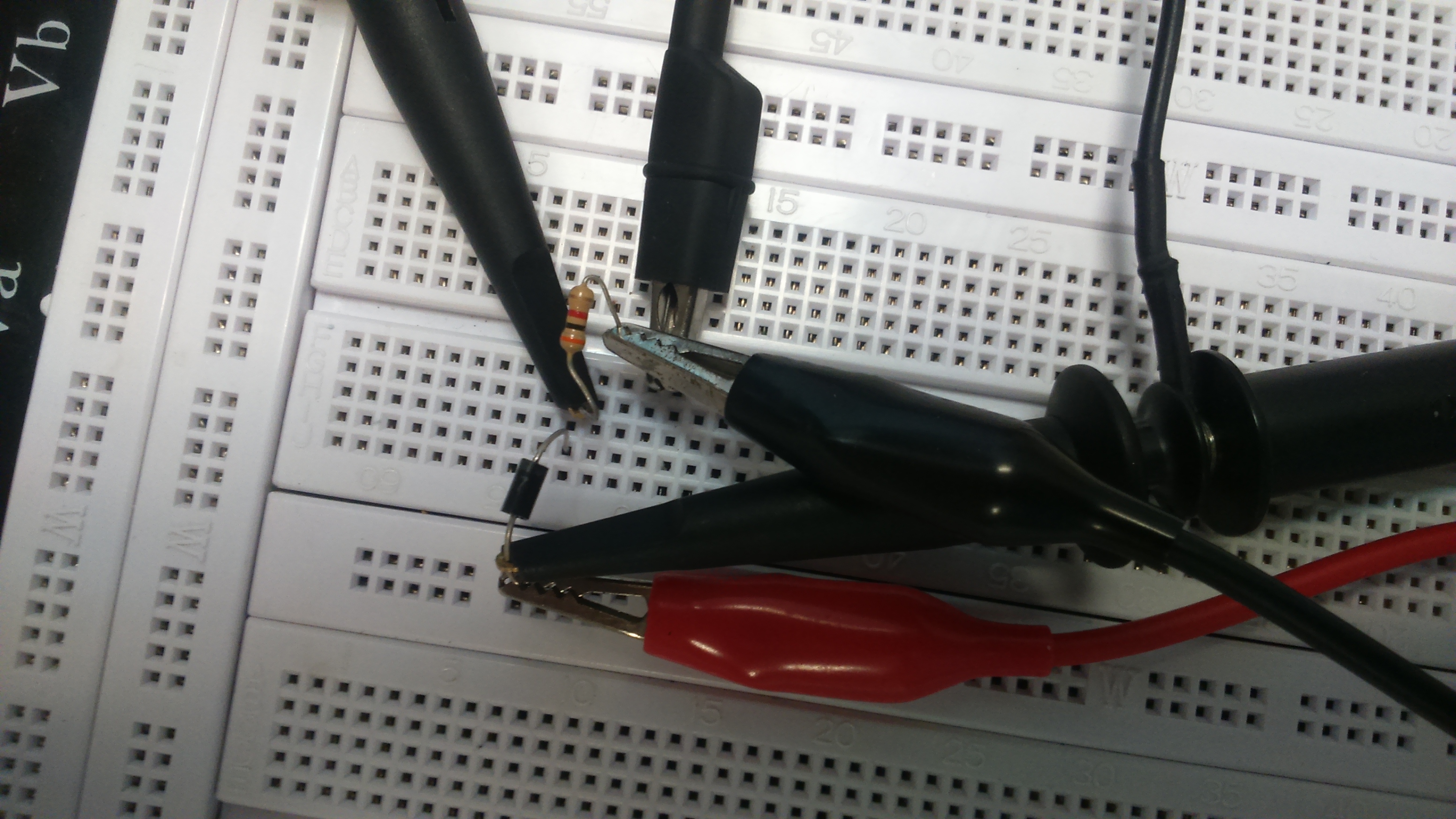
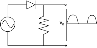
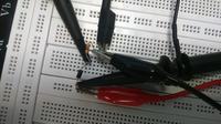
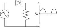
I'm testing a very simple circuit: half-wave rectivier composed by 1N4148 + Rload (3 Kohm), using protoboard.

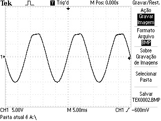
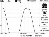
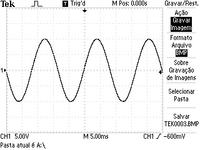
When I connect a capacitor in parallel with the resistor, the INPUT curve (measured between the power supply and ground) changes as can be seen in the attached files.
It seems that the positive peak starts to be "cuted". I also included a zoom in this peak.

It does not make sense for me. Does anyone have an explanation for that?

Thank you very much. Best regards,


The RC time constant must be at least 5x the period of each half cycle.

- - - Updated - - -

The generator source that impedance will result in current pulses only at the peaks from the Diode resistance and capacitor ESR which loads the generator 50R during that pulse. Since the peak drops about 10% I estimate your diode resistance is 10% of 50R. The effective series resistance of the diode drops with rising power rating of the diode such that the product is constant over all ranges of diodes.
 
Aren't you asking, "Why is the top of the input sinewave chopped off?"
The diode draws a very high current for short durations to top-up the voltage on the capacitor. The sinewave source has series resistance so its peak voltage drops a little as you can see when the diode conducts.
 
Yes.. my question is exactly it: "Why is the top of the input sinewave chopped off?"

I though about the sinewave source resistance (Rs)... but why does it only happen for the positive pulse?

As you can see.. the negative pulse is not chopped off. The source resistance and the current provided is the same.

It would mean that the source resistance (Rs) would be different for positive and negative peaks. I would not expect it.
What is "cuted"?

The source resistance doesn't change but the current does, which affects the voltage.
The positive and negative peaks are different because the diode allows current to flow only on the positive peak, so the source resistance only has an effect on the voltage during that time.
Since no current flows during the negative part of the cycle, the source resistance has no effect on that voltage.
 
The RC time constant must be at least 5x the period of each half cycle.

- - - Updated - - -

The generator source that impedance will result in current pulses only at the peaks from the Diode resistance and capacitor ESR which loads the generator 50R during that pulse. Since the peak drops about 10% I estimate your diode resistance is 10% of 50R. The effective series resistance of the diode drops with rising power rating of the diode such that the product is constant over all ranges of diodes.


Your voltage source does not have 0 Ohms or low enough to retain the sine shape.ac.jpg

see here

https://www.falstad.com/circuit-jav...9.765625E-55+0+-1 o+5+32+0+35+5.0+0.025+0+-1
 
Status
Not open for further replies.

Similar threads

Part and Inventory Search

Welcome to EDABoard.com

Sponsor

Back
Top