Continue to Site

Welcome to EDAboard.com

Welcome to our site! EDAboard.com is an international Electronics Discussion Forum focused on EDA software, circuits, schematics, books, theory, papers, asic, pld, 8051, DSP, Network, RF, Analog Design, PCB, Service Manuals... and a whole lot more! To participate you need to register. Registration is free. Click here to register now.

8x8 Dot Matrix LED pull up resistors?

Status
Not open for further replies.

5arid

Member level 1
Joined
Jan 23, 2016
Messages
32
Helped
0
Reputation
0
Reaction score
0
Trophy points
6
Activity points
279
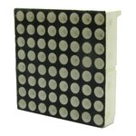
I designed a 8x8 Dot Matrix LED :

8x8LED.jpeg

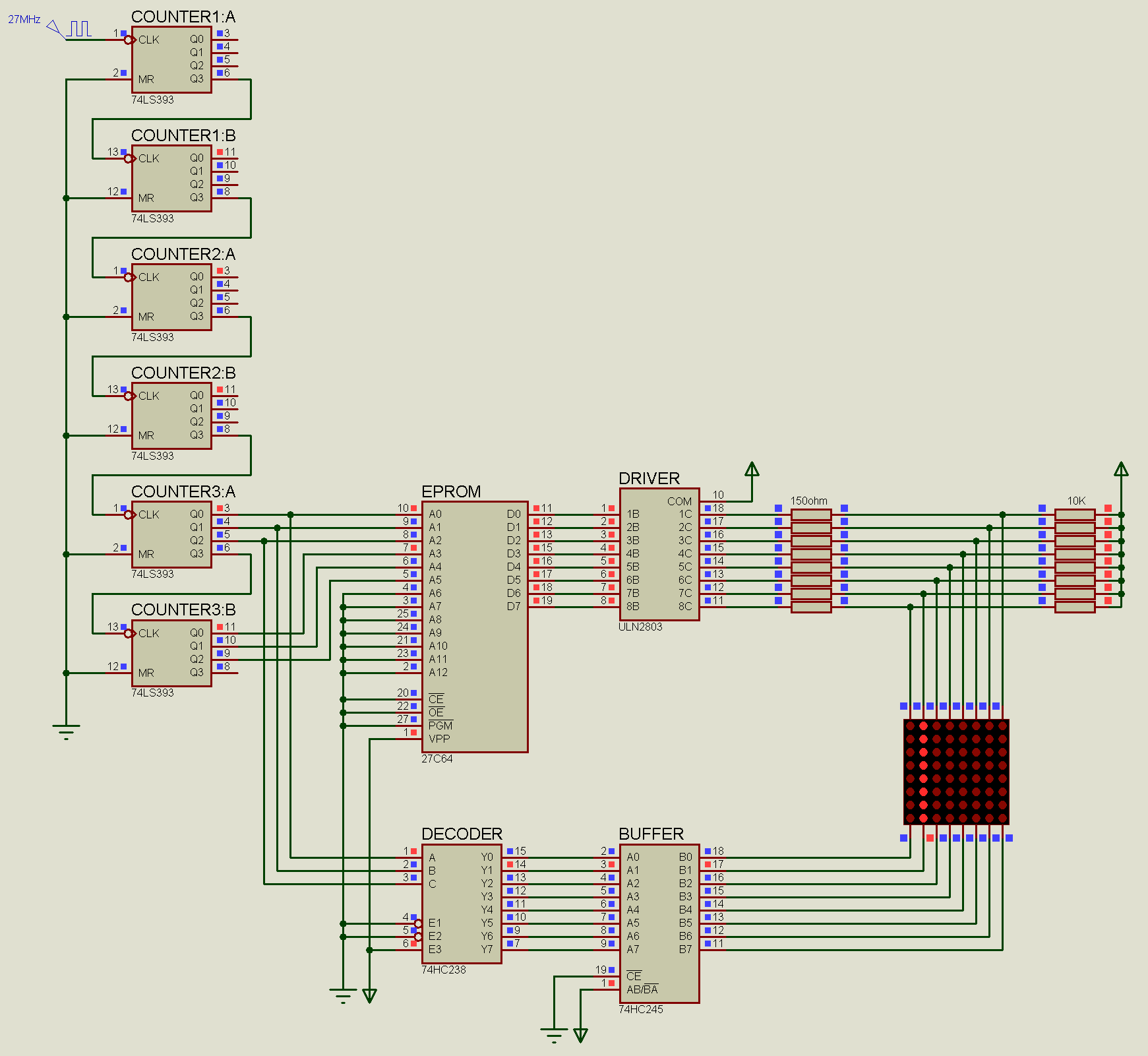
And here is the schematic :

schematic.PNG

It works fine.

But I see that in some other schematics there are pull up resistors :

pull_up_res.jpg

Do I need those pull up resistors?

Thanks in advance
 

No you don't. They needed only for digital simulation because led matrix used as a digital primitive combined with analog model of 2801. This is crap))) do not repeat it.
 

There is also another problem with my design :
The LEDs are not bright enough.
How can I fix it?
By the way I am using 150 ohm for current limiting resistors.
 

Agreed, and the +5V connection to the ULN2823 isn't needed but a ground connection to pin 9 absolutely is. Pin 9 is NOT a power supply connection, that device does not need any internal power, strictly speaking is the current output pin.

Brian.

[edit]
For more brightness your best approach is to use a driver (such as the ULN or even using single transistors) to allow more current to sink to ground. The HC245 is designed to provide fairly high current but the HC138 isn't a good current sink. It would also give you protection against reverse voltage on the LEDs, at the moment, if the outut of the 245 is low and the 138 is high, there is reversed voltage across the LEDs!

Brian.
 

No, he just using dinamic indication. And the duty cycle is too low (1/8). To get more brightness he have to use static, but it is obviosly impossible here.
 

How about this one :

led02.PNG

Added ULN2803
Added pull-up resistors
Replaced 138 with 238 (for inverted output to be used with ULN)

Will it work?
Any other suggestion?
 

Hi,

for a 1/8 duty cycle you need 8 times of current in times when LED is ON to get the same brightness. (as long as this is allowed by the datasheet)


Klaus
 

It's better.

The current through each LED is, assuming 1.6V per LED, (5-1.6)/150 = 23mA and the combined current if all LEDs in one column would be 8 * 23mA = 181mA, thats why I suggested it may be too much for a HC138 to sink. To get even better brightness your only options are to increase the current (drop the series resistor value) or change the whole driver part so the LEDs are driven statically. That will need quite a lot more circuitry though. Be careful if you drop the resistors because you are already pushing the HC245 quite hard, you may have to use drivers on it's output to increase its current capability.

Brian.
 

one of my friends suggested to connect /OE (EPROM) to Q3 (Counter2:B)
But as I tested I didn't notice any change.
Is there any advantage with that?
 

No advantage at all.

The problem is the relative time the LEDs are on to off. The '138 (or '238) is decoding a count on its ABC pins so that each of it's outputs goes active in sequence. The active output is one of 8 pins, the others are inactive, that means only 1/8th of the time is spent illuminating a driven LED and 7/8ths of the time is spent with it turned off. Although the LEDs are being driven at 23mA, which is probably their maximum rating, the relatively short period they are lit up gives the perception of them being dimmer than they really are. Other than changing the driver circuit so each column is individually latched, the only other alternative is to overdrive their current. That may violate the manufacturers rating but it is commonly done without harm because the failure mode of most LEDs is from overheating and as you are only driving them 1/8th of the time, the amount of heat dissipated in them will be proportionately lower.

Brian
 

I am controlling LED anode with EPROM and LED cathode with 238 :
EPROM --> Buffer --> Anode
238 --> Driver --> Cathode

But it seems that it is possible to swap the cathode and anode circuits :
238 --> Buffer --> Anode
EPROM --> Driver --> Cathode

Which setup is better?
Is there any difference between them?
What about for current limiting resistors, is it better to put them near Buffer or Driver?

I am asking because I have two different Dot Matrix LED which their pinout are completely different.
 

Attachments

  • 01.jpg
    01.jpg
    43.6 KB · Views: 102
  • 02.jpg
    02.jpg
    53 KB · Views: 112

The output of the '238 is sequential so you would have to use it to drive an entire row or entire column, regardless of whether the LEDs were common cathode or common anode.

Regarding the resistor, consider this: each '245 out (maybe through a buffer) only lights a single LED at a time. The '138/'238 (maybe through a buffer) has to carry the combined current of all the LEDs turned on in that column. So if you put the resitor in the '245 line you only get the voltage drop in the resistor due to 1 LED and it's brightness will be constant. If you put the resistor in the '138/'238 side, the voltage dropped by the resistor will vary according to how many LEDS are lit up. The more LEDs you have turned on, the dimmer they will all be.

Brian.
 

How about this one :


It would still be the same, it is the method of driving (multiplexing) the LEDs, not the circuit that has the deficiency.

Incidentally, although an experienced person would recognize how it works, it would be more intuitive to draw the diagram so the rows were fed at the side of the matrix and the columns from the top or bottom.

I'm not sure if you know but there is a single IC that can drive all 64 LEDS. Look up MAX7219 and MAX 7221, it can be configured to drive any combination of 7-segment or individual LEDs and has all the driver circuits inside it. You would have to serialize the data to make the dot patterns but that isn't too difficult.

Brian.
 

Will it work - Yes.

Will it work as you expect - No!

The brightness will be even lower, in fact several times lower. The fundamental problem is the LEDs are not lit up for long enough. If you pass a steady current through an LED it will be as bright as expected. If you pass the same current through the same LED but only pulse it on for 1/8 of the time and off for 7/8 of the time, visually it will appear much dimmer. That is why your original circuit is not bright enough. When you expand it to 8 matrix modules, the time each LED is on drops to 1/64 of the time and 63/64 of the time it is off. The brightness therefore will be approximately (perception of vision is not linear) 8 times lower than before.

Look at it this way: to get flicker free multiplexing, most systems use around 500Hz scan rate, that means it takes 2mS to go from activating the LEDs in the first column to activating the ones in the last column. You have 64 columns so each one will only be active for 2/64mS = 3.1mS. To see the approximate difference in brightness, run an LED at 20mA continuously then drop the current to 0.3mA, that will be about the same difference in brightness you would see in a 64 output multiplexer.

Brian.
 

the time each LED is on drops to 1/64 of the time and 63/64 of the time it is off.

So I have to use lower resistor for current limiting?

Hi,
for a 1/8 duty cycle you need 8 times of current in times when LED is ON to get the same brightness. (as long as this is allowed by the datasheet)
Klaus

5v Source voltage
2v diode forward voltage
25 * 64 diode forward current (mA)

So according to www.ledcalc.com : R = 2.2 ohm 5 wat

Is this right?
 

Yes, but the driver IC and the LEDs would burn out!

5V source - 2V diode drop = 3V across the resistor.
Current = V/R so it would be 3/2.2 = 1400mA through the LEDs. They are probably only rated a 30mA.

What you really need to do is drive the LEDs in a different way. The method used by moving sign boards is to divide the problem in to smaller sections of LEDs. Using high brightness LEDs you can see enough brightness if you wire them in an array of 8x8. You then drive each group of 8x8 through it's own driver circuit so they are all scanning at the same time instead of one after the other. The problem for you is that you only have one path from the EPROM to the LEDs, to be able to drive each 8x8 matrix at the same time, they each need their own data path. You can do it using several EPROMs and drivers, one for each matrix or by using one EPROM and reading the data for each matrix from it and storing it in a latch. Either way will make the schematic more complicated.

The method Maxim use in their driver ICs is to hold the data for all the LEDs in an internal memory and continuously read it out. One MAX7219 will drive 64 LEDs but it does all the work for you, just wire the LEDs to the IC and tell it what to display, even if you disconnect the data lines to the MAX7219 it will keep the same pattern on the LEDs. The problem for you would be getting the data from the EPROM to the MAX7219s because they are serial programmed through an SPI (or Microwire which almost the same) interface. It's easy with a microcontroller but more difficult in discrete ICs.

Brian.
 

Hi,

if I understand the circuit right, then there is a duty cycle at each LED of 1/64,
If rated for 30mA DC, it is not unusual to drive them with 1400mA and 1/64 duty cycle.

But many LEDs - rated with 30mA DC current - are rated for 1A pulse current.. but driving a LED with 1.4A pulsed current will result in bad efficiency, caused by the influence of ohmic power dissipation within the LEDs.
Expect increased heating and less brightness.

I don´t recommend to drive LEDs with a duty cycle of 1/64. --> 1/8 is good.

In either case: read the LED datasheet to find out if the LED is rated for your desired pulse current (and pulse duration).

Klaus
 

Status
Not open for further replies.

Part and Inventory Search

Welcome to EDABoard.com

Sponsor

Back
Top