Continue to Site

Welcome to EDAboard.com

Welcome to our site! EDAboard.com is an international Electronics Discussion Forum focused on EDA software, circuits, schematics, books, theory, papers, asic, pld, 8051, DSP, Network, RF, Analog Design, PCB, Service Manuals... and a whole lot more! To participate you need to register. Registration is free. Click here to register now.

R2R DAC(ditital to analog converter) disadvantage (VCR, LSB)

Status
Not open for further replies.

020170

Full Member level 4
Joined
Jan 31, 2005
Messages
231
Helped
3
Reputation
6
Reaction score
1
Trophy points
1,298
Activity points
2,221
I tried to design R2R DAC structure at in my circuit.

In my thought R2R DAC is more area effective DAC than conventional R-String DAC.

However, R2R DAC has some disadvantages.

1. VCR Issue
- In CMOS process, poly-silicon resistor or diffusion resistor has voltage coefficient. that is to say, resistor value is dependent for voltage across resistor.
It is not important for R-string DAC because all resistors of R-String DAC has same voltage potential, so VCR does not important.
However, resistors of R2R DAC has different voltage potential, especially it is dependent for digital input code. it caused several INL error issue.

2. LSB Issue( or Not full swing Issue)
- R-String LSB is very simple. for example 10bit DAC, 1 LSB is equal to " VDD / (1023) "
However R2R DAC LSB is equal to " VDD / (1024) "
It means R2R DAC does not output specific analog output, VDD or GND. How can I compensate?

Thanks.
 

Hi,

It means R2R DAC does not output specific analog output, VDD or GND.
On the one side you bother about this less than 0.1% of difference
And on the other side you use VDD as reference... but usually VDD (supply voltage) changes in the range of some %.
What DNL and temperatre drift errors do you expect? Less than 0.1%?
DNL and INL of a R2R DAC will be better than on an R string DAC.

How can I compensate?
Both DAC have a relatively high output impedance. Therefore in many cases you need an amplifer at it´s output.
You may adjust the gain of the amplifier ot compensate for this......
BUT you might run into problems when you try to precisely generate a gain of 1024/1023.

***
My recommendation:
* first specify your DAC values. (Speed, range, DNL, INL, noise, ...)
* Then find out wich solution is best for your application
* Then try to improve the preferred solution on that error that causes highest error rate (I don´t think it´s the 1024/1023 problem)

Klaus.
 

I won't expect a precision DAC (not even 10 bit type) to use silicon resistors. Industrial products use thin film resistors.
 

Thanks for your reply.

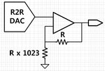
Oh. I miss it. Yes. as you can say that, if I use gain 1024/1023 buffer, I can solve LSB issue. However, for simple non-inverting gain control, I have to use 1 + 1023 resistor cells.

screenshot.52.jpg

Because I have very small area in my chip, if I use 1 + 1023 resistor cell for gain control, R2R DAC is not good choice for me. It is too huge for me...
Is there any other solution for LSB issue except gain of 1024/1023?


My DAC specification is below

Resolution : 10Bit
DNL : 0.3 under
INL : 0.3 under
Area : Very Small
Speed : Not Important
Temperature drift : not important
Range : Not Important (If I use 2x or 3x gain control, it does not important)
Noise : Not Important

The reason that I want to design R2R DAC, R2R DAC is more area efficient than R-String DAC. R-String DAC has too many signal line. (10Bit R-String, Signal line number is 1024, layout so complicated.)
INL and DNL is important for me. But as you can see, most important for me is DAC size, that is, "Cost". :)
For very small area size, I don't want to use any auxiliary opamp for DAC.

When I search web about VCR issue, I search some article. but I don't understand about that.

link : https://www.designers-guide.org/Forum/YaBB.pl?num=1314669361

user "carlgrace" say like that :

As for voltage coefficient, generally resistors made of n and p materials have opposite signed voltage coefficients. So, once you choose a value of resistance, you can do a couple of resistors in series to get nominal zero voltage co. Of course this isn't perfect in practice but it goes a long way. Most modern processes have both PPOLY and NPOLY resistors.

-> Negative voltage coefficient resistor + positive voltage coefficient resistor mixed is very simple approach for VCR issue. But I wonder it is "practical approach" for VCR issue. I'm not sure that resistor mixed approach is really reliable or not.

So, my advice is do oversampling. If you don't want to or can't, do a current-source DAC. And don't be afraid to segment if you're in an older technology. If its deep submicron, brute-force that sucker.

-> oversampling is effective approach for VCR issue?? I don't understand the relation between oversampling and VCR. and I don't understand "segment" too.

thanks.

- - - Updated - - -

I won't expect a precision DAC (not even 10 bit type) to use silicon resistors. Industrial products use thin film resistors.

But... Some industrial products have good INL/DNL characteristics, they use only standard poly-silicon resistor. :)
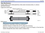
Foundry company(like TSMC) provides thin film resistor with me without additional mask layer? and How about thin film resistor VC(voltage coefficient) and TC(temperature coefficient), Rsh(sheet resistance)?

screenshot.54.jpg

In my search, Rsh of thin film resistor is too small. For appropriate resistor value, I have to use too long length for thin film resistor. I don't think so thin film resistor is good resistor type for R2R or R-String DAC.
 
Last edited:

Status
Not open for further replies.

Similar threads

Part and Inventory Search

Welcome to EDABoard.com

Sponsor

Back
Top