Continue to Site

Welcome to EDAboard.com

Welcome to our site! EDAboard.com is an international Electronics Discussion Forum focused on EDA software, circuits, schematics, books, theory, papers, asic, pld, 8051, DSP, Network, RF, Analog Design, PCB, Service Manuals... and a whole lot more! To participate you need to register. Registration is free. Click here to register now.

An issue with a light detection circuit

Status
Not open for further replies.

ADGAN

Full Member level 5
Joined
Oct 9, 2013
Messages
295
Helped
4
Reputation
8
Reaction score
4
Trophy points
18
Activity points
1,837
Hi! I made an alarm circuit that is control by a light sensor. This light sensor is made out of a LDR, Transistor(2N3904) and a couple of resistors as shown below. When I constructed the circuit on a breadboard it worked fine. But when I build it on the PCB it doesn't clearly recognize darkness. i.e. when in darkness still the alarm circuit is on when it should be off. What could be the reason for this? I tried changing the resistor to 330R but still the same. Could this be because of a faulty LDR?
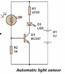
Capture.PNG
 

When I constructed the circuit on a breadboard it worked fine. But when I build it on the PCB it doesn't clearly recognize darkness.
View attachment 128777

This sentence is really the key. It means that there is a mistake you made somewhere, or that you damaged a component during the soldering process.
Do you have a DMM? If so probe around for resistance values (non powered up) and voltages (powered up).
 

Hi! I made an alarm circuit that is control by a light sensor. This light sensor is made out of a LDR, Transistor(2N3904) and a couple of resistors as shown below. When I constructed the circuit on a breadboard it worked fine. But when I build it on the PCB it doesn't clearly recognize darkness. i.e. when in darkness still the alarm circuit is on when it should be off. What could be the reason for this? I tried changing the resistor to 330R but still the same. Could this be because of a faulty LDR?
View attachment 128777

Try first to wash your board with alcohol. The sensitivity can be adjusted by the resistor connected from transistor base to ground- the smaller its value, the less sensitivity. If nothing helps, the light sensor might be damaged by soldering. Replace it with a new one.
 

Also,,,, add a resistor (470 to 1k) in series with the LDR.

I've measured LDRs that have a resistance lower than 100 ohms in bright sunlight. Too much current will flow in that instance, and you can damage either the LDR or the transistor.
 

This sentence is really the key. It means that there is a mistake you made somewhere, or that you damaged a component during the soldering process.
Do you have a DMM? If so probe around for resistance values (non powered up) and voltages (powered up).

Thanks. Yes I have a DMM. What is the resistance or voltage value I should expect?

- - - Updated - - -

Try first to wash your board with alcohol. The sensitivity can be adjusted by the resistor connected from transistor base to ground- the smaller its value, the less sensitivity. If nothing helps, the light sensor might be damaged by soldering. Replace it with a new one.

Thank you. I'll try replacing one.

- - - Updated - - -

Also,,,, add a resistor (470 to 1k) in series with the LDR.

I've measured LDRs that have a resistance lower than 100 ohms in bright sunlight. Too much current will flow in that instance, and you can damage either the LDR or the transistor.

I can't add another resistor now. I might have to replace with a 1.5k resistor. Generally how do we calculate these resistor values?
 

As your light indicator worked well on a breadboard, something has happened by soldering. Check the transistor and LDR, other components see to be OK. Test also the LED, some are sensitive to soldering temperature.

To calculate resistor values, use the DVM to measure its resistance at max light and dark. From this and the R1 you can check transistor opening and closing.
 
  • Like
Reactions: ADGAN

    ADGAN

    Points: 2
    Helpful Answer Positive Rating
You have an LDR to detect light and an LED as an alarm that makes light. Does the LDR "see" light from the LED? If it does then it will never turn off.
 

You have an LDR to detect light and an LED as an alarm that makes light. Does the LDR "see" light from the LED? If it does then it will never turn off.

I have a LED with an alarm circuit. The LDR and LED is far away. Even when the LDR is fully closed it still detects light.
 

Can you measure the the resistance of the LDR in light and in dark? Also check the PCB traces are clean...
 

Can you measure the the resistance of the LDR in light and in dark? Also check the PCB traces are clean...

I measured the resistance, when there is light its about 0.3k and when there its dark about 0.3M.
 

I measured the resistance, when there is light its about 0.3k and when there its dark about 0.3M.

Please check the PCB, clean once again and try once more. The LDR is working fine as expected. Please check the transistor connections. Please also see that there is nothing that can short in between the PCB tracks.

I cannot think of anything that can go wrong in the circuit...
 

It should be any wrong connections in the PCB. As you said it is worked fine in the bread board the same is expected in the PCB too. Trace the connections node to node using DMM.
 

Please check the PCB, clean once again and try once more. The LDR is working fine as expected. Please check the transistor connections. Please also see that there is nothing that can short in between the PCB tracks.

I cannot think of anything that can go wrong in the circuit...

It should be any wrong connections in the PCB. As you said it is worked fine in the bread board the same is expected in the PCB too. Trace the connections node to node using DMM.

Thank you. I think there is a short somewhere. I tried replacing the LDR and still no good. Even when the LDR is removed still the alarm turns on with a low volume :(
 

The 1k resistor between the base and emitter of the transistor should turn it completely off without the LDR. Even with the LDR, the current in the 300k LDR and 1k resistor is 6V/301k= 19.9uA then the voltage across the 1k resistor is 19.9uA x 1k= 0.0199V but a silicon transistor needs a base-emitter voltage of 0.5V or 0.6V to begin turning on. Then you must have a bad transistor, have its pins mixed up or the 1k resistor is broken.
 
  • Like
Reactions: ADGAN

    ADGAN

    Points: 2
    Helpful Answer Positive Rating
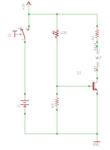
Thank you for the replies. I tried removing the LDR and the transistor but still the alarm circuit turn on slightly with a lower volume. I'm finding it difficult to identify the fault in the circuit. I have posted the schematic and the PCB board, if there is any fault that I couldn't see for my myself, I would really appreciate if anyone of you could point out.

Capture.PNGpcb.png
 

Status
Not open for further replies.

Similar threads

Part and Inventory Search

Welcome to EDABoard.com

Sponsor

Back
Top