Continue to Site

Welcome to EDAboard.com

Welcome to our site! EDAboard.com is an international Electronics Discussion Forum focused on EDA software, circuits, schematics, books, theory, papers, asic, pld, 8051, DSP, Network, RF, Analog Design, PCB, Service Manuals... and a whole lot more! To participate you need to register. Registration is free. Click here to register now.

Can I use TIP122 instead of electromechanical relay ?

Status
Not open for further replies.

pic.programmer

Advanced Member level 3
Joined
Aug 19, 2015
Messages
773
Helped
141
Reputation
284
Reaction score
140
Trophy points
43
Activity points
7,531
Can I use TIP122 instead of electromechanical relay ?

I am making a battery charger using PIC18F26K22. The battery is charged from solar panel. I want to know two things.

1. What should be the current rating of the solar panel ?

Solar Panel is 12V and battery is also 12V.

The battery is charged in two modes, boost and trickle charge modes.

In trickle charge mode the relay makes a lot of noise and hence I want to replace it with a power transistor or mosfet.

Can I use TIP122 instead of the relay ? Is power mosfet a better solution ? If yes, which mosfet can I use.

Please provide a circuit for connecting mosfet between solar panel and battery.
 

Attachments

  • SSC.png
    SSC.png
    96.5 KB · Views: 156
  • SSC 2.png
    SSC 2.png
    38.5 KB · Views: 61

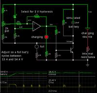
I used an N-mosfet to control PV panel charging to my batteries. It charged continually until the battery reached 14.4V. Then it turned off. The battery settled downward about a volt. Then the charger cycled on (for a minute) and off (several minutes). Not quite as good as a genuine taper charge, but the next best thing.


The circuit I built had a mosfet. The simulation shows a transistor (rather than a mosfet), because I've found the transistor model gives less uncertainty about biasing.

1. What should be the current rating of the solar panel ?

A battery stays at maximum health if kept fully charged. Try to do this by the end of each day. You can get by with less power if you only partially discharge the battery each day. However keep in mind there will be spells of weather that require two days of charging.

I had 64W panels. In bright sun one could push about 3.5 A into a 12V battery.

Consider that you'll have unfavorable conditions. In winter the sun is low in the sky, and for a shorter time. You might only have a few hours for a charge session.

Anyway the answer is to calculate the A-hrs of the battery, and calculate so many A-hrs worth of charging.
 
TIP122 is a darlington with a back diode built in so it will drop about 1.2V, thus for 2A thru current it will dissipate ~ 2.4 watts, so will need a proper heat sink if you want to avoid it dying to a short.

The relay is a better solution for low losses, assuming it does not need to switch too often.
 
The relay is making a lot of noise and hence I want to replace it with power transistor or power mosfet. Can I use IRF810 Mosfet ? Can somebody provide IRF810 Mosfet circuit ?

- - - Updated - - -

I searched and found that IRF840 N Channel MOSFET can be used. Its max Drain Current is 8A and VDS is 500V. I am doing 4 versions of the battery charger. They are for 12V, 24V, 36V and 48V. So, for 12V type I am using LM7805 regulator to power the PIC and for the other three battery chargers I am going to use LM2576HVT-5.0 regulator. It can take max 60V input and provide 5V 3A output.

The charging current for battery will be max 3.2A and so the IRF840 can easily handle it.

Please provide biasing circuit for IRF840.

Please see the image and tell me if the circuit is correct. I have used 6A diode to block the battery voltage flow into solar panel.

- - - Updated - - -

How to calculate Drain to Source resistance ? Datasheet says it is 0.85E for VDS = 10V. My VDS will be max 52V. I need to know the RDS at 52V so that I can use IIR formula to calculate the power dessipated by the IRF840. I is 3.2A.
 

Attachments

  • SSC 5.png
    SSC 5.png
    33.9 KB · Views: 62
Last edited:

IRF840 = .85 ohm (at 20C) x 3.2A = 2.72 V on drop, x 3.2A = 8.7watts dissipation, assuming you can keep the device to 20C, so it will blow up fairly soon after turn on with this current, for a dissipation of 0.5W say you need a fet with Ron <= 48 milli-ohm @ 100C, 32 milli-ohm @ 20C
 

Attachments

  • 75017357.pdf
    3.3 MB · Views: 70
Last edited:

Hi,

Each manufacturer has interactive selection guides on their web sites.
Look for
* VDS as you like. 100V is a good start. With a good layout 60V will be sufficient. With a bad layout even 100V will not be enough
* Rds_on less than 50mOhms @ your gate_drive_voltage.. If you don'find any you need to go higher, but you may have increased power dissipation = heating
* current rating >= 4A
* thermal resistance: less than 40K / ( I x I x Rds_on).

Klaus
 
Status
Not open for further replies.

Similar threads

Part and Inventory Search

Welcome to EDABoard.com

Sponsor

Back
Top