Continue to Site

Welcome to EDAboard.com

Welcome to our site! EDAboard.com is an international Electronics Discussion Forum focused on EDA software, circuits, schematics, books, theory, papers, asic, pld, 8051, DSP, Network, RF, Analog Design, PCB, Service Manuals... and a whole lot more! To participate you need to register. Registration is free. Click here to register now.

Relay Contact Sticking Problem when start 1HP AC Motor

Status
Not open for further replies.

asking

Full Member level 5
Joined
Sep 21, 2010
Messages
279
Helped
6
Reputation
12
Reaction score
6
Trophy points
1,298
Activity points
3,377
Capture.JPG

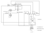
In the Image... i am trying to put 30A 12V Relay OMRON G8P-1A4P 12VDC parallel to Push Start Button (Dual Starter control for 1HP Pump Motor). But every time relay picks up contact stick... Before using Relay i was using 25A 24-480VAC SSR (Zero Crossing) but 4-5 of them failed due to large Surge / Inrush current. So i switched to Relay. But now relay contacts are sticking.

I also tried to add RC Snubber 0.1uF 600V + 66 Ohms but did'nt help.

Please suggest some idea how i can i avoid Arcing. Relay contact are rated for 30A / 250VAC my load is max 20A for just 0.5-1 Second. Then contactor picks up and motor is operated through Contactor. No load is given to relay later on.

Please suggest...me a Quick way to overcome this problem
 

yes but at start up, the motor would consume 7times more current which is about 140A. This would obviously stick the relay contact.
 

yes but at start up, the motor would consume 7times more current which is about 140A. This would obviously stick the relay contact.

Ammeter shows 20A only for 1 Second and then its normal 7-8Amp @ 230VAC.
 

n the case of motor starting, if the power source voltage drops, and during the humming of the relay, if it reverts to the restored condition, the contacts suffer a burn damage and welding, with the occurrence of a false operation self-maintaining condition.
 

Between relay contact and pin 1 of J1 insert a 4-5ohm / min 40-50W resistor in paralel with a contact relay that is open only for start-up time (only time as you push ON button).
This will reduce start-up current from 100-120Amp to maxim 20-25Amp. This is ok if your pump start-up with no load or a small load, because start-up torque is reduced.
 

The relay contacts are most likely welded when discharging the capacitor during contact closure, a natural result of the strange design.

But the schematic in post#1 seems somehow confused, a readable schematic should show input voltage and motor terminals.
 

@FvM : when discharging capacitor happen? Are them charged?
 

I would prefer to see a corrected schematic before answering the question.
 

The circuit seems to be unconventional. With a start and run capacitor, the start capacitor is normally disconnected by a switch on the motor shaft, so at 75% shaft speed the switch opens and only the run capacitor stays in circuit. With this design , you don't know how long to hold the start button in, so the start capacitor can be putting an excessive amount of current through the start winding - causing the relay contact problem?
Frank
 

Status
Not open for further replies.

Similar threads

Part and Inventory Search

Welcome to EDABoard.com

Sponsor

Back
Top