Continue to Site

Welcome to EDAboard.com

Welcome to our site! EDAboard.com is an international Electronics Discussion Forum focused on EDA software, circuits, schematics, books, theory, papers, asic, pld, 8051, DSP, Network, RF, Analog Design, PCB, Service Manuals... and a whole lot more! To participate you need to register. Registration is free. Click here to register now.

SPI problem in eeprom pic16f151x

Status
Not open for further replies.

BiNa2605

Full Member level 3
Joined
Sep 1, 2015
Messages
179
Helped
6
Reputation
12
Reaction score
4
Trophy points
18
Location
VietNam
Activity points
1,357
I want to interface with EEPROM of (sensor tag UHF RFID) using MCU Microchip by applying SPI. But I cannot write data into EEPROM of sensor tag. These are my code:
Code:
#define  SEN     PORTC.B1
#define  WRITE   0x0000
#define  READ    0x4000
#define PAGE_WR  0x0800
unsigned int uiTemp=0;


//Write function for the SPI interface
void SL900A_Write(unsigned int uiMode, unsigned int uiAddress, unsigned char ucData){
     SEN = 1;              //Enable Slave select
     delay_us(500);          //SEN to first SCLK rising edge setup time
     //Transmit 16 bit data
     uiTemp = (uiMode&0xff00) | uiAddress;
     SPI1_Write(uiTemp);
     SPI1_Write(ucData);                        //Data need to transmit
     delay_ms(1);
     SEN = 0;                                   //Stop
}

void main()
{
     unsigned char ucwrData, ucMo;
     unsigned int uiMo, uiAdd,i,uiTemp1;
     
     //FOSC = 0b110; INTOSC oscillator
     //OSCCON = 0b01011010;           //Internal Oscillator 1Mhz --- SL900A -> 1.5v
     //OSCCON = 0b01101010;           //Internal Oscillator 4Mhz
     OSCCON = 0b01110010;         //Internal Oscillator 8Mhz
     //OSCCON = 0b01111010;         //Internal Oscillator 16Mhz
     TRISC.B1 = 0;          //RC1 output Select SPI
     PORTC.B1 = 1;
     TRISB.B4 = 0;          //RB4 output test led
    
     //SPI
     SPI1_Init_Advanced(_SPI_MASTER_OSC_DIV4, _SPI_DATA_SAMPLE_MIDDLE, _SPI_CLK_IDLE_LOW, _SPI_LOW_2_HIGH);
     //SPI1_Init();
     //Choose MODE in here
uiMo = WRITE;
     //uiAdd = 0x047E;      //the last physical address of SL900A User_Memory
     uiAdd    = 0;      //The first physical address of SL900A User_Memory
     ucwrData = 0x01;
     
     for (i=0;i<100;i++){
             SL900A_Write(uiMo,uiAdd+i,ucwrData);
             delay_ms(1);
        }
     while(1){
        PORTB.B4 = 0;
        //delay_ms(100);
        //PORTB.B4 = 0;
        //delay_ms(100);
     }
}
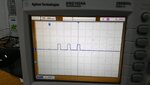
But it is not work. And then the datasheet and memory of this eeprom
Mode.PNG
SPI_Timing.PNG
SPI_Timingfor3V.PNG
SPI_WriteMode.PNG
UserMemory.PNG
 

SPI command needs two byte writes. You are only writing the low byte.

Code:
     SPI1_Write(uiTemp >> 8);
     SPI1_Write(uiTemp);
 
Hi,

We need more information.(HF RFID is wireless, not SPI)
What EEPROM device is it?
Does it contain a write protect feature? (Sw or hw)
Are there other devices on the SPI bus?

****
Klaus
 

That is UHF RFID SL900A it include the SPI to interface with MCU and EEPROM to store the data.
MCU connect.PNG
Memory.PNG

- - - Updated - - -

I measured the signal of SPI interface using Oscilloscope
Measure by Oscilloscope.jpg

when I compare it to the Application note, it is so different.
SPI write single byte.PNG
 

Please describe what traces 1 and 2 are on your oscilloscope picture. The waveforms look completely wrong but without knowing which signals they are, what data is being shown and the time scale it isn't possible to make a good diagnosis.

Brian.
 

HI,

maybe you don´t have a proper GND signal at your scope probes.

Maybe the PORT IO setup (input/output) of your microcontroller is not correct.

Klaus
 

SCLK.jpg

The pink line is the signal from SLCK pin and the blue one is the SS (Slave select pin).

- - - Updated - - -

SLCK_1.jpg
I do not know why when I observate the signal in the Data out and signal in the Slave select. They have the same signal. :(

- - - Updated - - -

When comparing to the reference. SLCK is right but the SEN (SS) and DIN is wrong.
 

Attachments

  • SCLK.jpg
    SCLK.jpg
    297.6 KB · Views: 136

It looks like you are not actively driving the SEN pin or you are using a pin that is not configured as a digital output. The waveform suggests the low logic state is being pulled to 0V but the high state is floating. Check which pin SEN is assigned to and whether it is configured as an output bit.

Note that you have to drive the select signal from a port pin, the 'slave select' is an input to the PIC so it can be used as an SPI peripheral by another device.

Brian.
 
I am sure that I set that pin is digital output. I am consider about hardware.
 

Another thing to check is the ANSELA register. Your diagram show you are using the pin called /SS which can be RA0 or RA5 depending on the alternate pin configuration but both are on PORTA. The SDI and SDO pins are shared with PORTC. By default PORTA is configured for analog input, have you ensured the ANSELA bit corresonding to your select output is '0' (digital mode)?

Brian.
 

Oh, I do not know that I have choose the SS pin (in the PortA). How about when I choose the PortC for the chip select pin? Is it wrong?
 

The important thing to remember is the data and clock are produced by the MSSP module inside the PIC but you have to select the device it is talking to with a 'select' signal you generate with your own code. So you have to use one of the I/O ports pins to select the device you are talking to, make sure it's configured as an output and write the code to drive it. You can use any of the pins as long as the hardware and software are using the same one. The idea is you can use the MSSP module to handle the clock and data signals and connect them to several devices, which device is active depends on the individual select signal you send to it.

Brian.
 
Thank you sir, I will fix my hardware and test it :thumbsup:.

- - - Updated - - -

Another thing to check is the ANSELA register. Your diagram show you are using the pin called /SS which can be RA0 or RA5 depending on the alternate pin configuration but both are on PORTA. The SDI and SDO pins are shared with PORTC. By default PORTA is configured for analog input, have you ensured the ANSELA bit corresonding to your select output is '0' (digital mode)?
The MCU operate at Master mode. So do I need to use SS pin or I just use optional pin for the chip select when applying SPI. I read the datasheet and some applications.
Simple answer: Hardware and software must match
I ask the using PORTC.B1 as an chip select is it wrong or right. Actually my hardware and software matched.

- - - Updated - - -

Now the signals are better.
clock and chip select.jpg

- - - Updated - - -

The above signal is CS-pink(chip select) and SCLK-blue of MCU.
That is the Dout of MCU :(Dout.jpg
 

The pin marked "/SS" only works when the MSSP peripheral is in slave mode.
In master mode you can select any I/O pin you like but you MUST drive it at the correct times yourself.
By the way, I would disagree that the scope traces are looking better. The bottom picture seems to have a signal that is varying by less that 200mV and it also has a huge level of noise. I would recheck the circuit from start to finish and make sure that it is correct, that you have a proper power supply, the voltage is correct, bypass capacitors are in place, the MCU has all of the required supply and other connections correct etc.
Susan
 
Last edited:

I use lithium battery (3.7V) as power supply for the MCU circuit and 3V for powering to sensor. This is my messy circuit.
Circuit.jpg
bypass capacitors are in place
Could you let me know the bypass capacitors. I do not know that.
 

By the way, I would disagree that the scope traces are looking better. The bottom picture seems to have a signal that is varying by less that 200mV and it also has a huge level of noise.
When I compare with the reference

SPI write single byte.PNG

The amplitude of SC pin (yellow is just 1V) and the SLCK amplitude is nearly 4V. In my case, the amplitude of SC pin is 400mV and the SLCK is nearly 2V.

- - - Updated - - -

The Dout signal is completely wrong.

- - - Updated - - -

Uhm, I am wrong, these signal have the same amplitude :(

- - - Updated - - -

How about in that code
Code:
for (i=0;i<100;i++){
             SL900A_Write(uiMo,uiAdd+i,ucwrData);
             delay_ms(1);
        }
I implement after run SPI1_Init();

The SPI interface run 1 time or 100 time ?

- - - Updated - - -

Now I think that the SEN pin and SLCK is ok :D
clock.jpg
 

I'm not sure why you run the routine 100 times but you may be seeing the signal lines rise nearer to their correct voltages by giving them longer to adapt. You only need to run the routine once.

As Susan and I have both pointed out, SEN (/SS) is NOT the signal to select an external device. It is only used in slave mode where the PIC itself is a slave to another SPI master. In yur application, the PIC is master so it has to geneate the select signals itself by driving one of the port pins. You can still use the /SS pin but only by treating it as RA0 or RA5 (check alternate pin register), configuring it as a digital output and driving it low only during the SPI transfer. In other words, it isn't being used as /SS but as an ordinary port pin.

All your logic signals should have fast rise and fall times (sharp edges) and be about 3.7V between low and high, even if they are single pulses.

Brian.
 

Hi Brian, after all do you know my problem? In my opinion the signal in CS and SLSK is ok, the problems I think that are the signal in the Dout of MCU or the time delay I use.
 

Status
Not open for further replies.

Similar threads

Part and Inventory Search

Welcome to EDABoard.com

Sponsor

Back
Top