preethi19
Full Member level 5
Hi all can someone pls explain constellation in a very simple basic way.
1)What is it?
2)When does it occur?
3)why is it used?
4)What do we understand from it?
Is it used for particular process like modulation or for any other purpose or in general for all communication systems???
I read once to design a good system we need to have the constellation diagram well so we can see how effiecient the communication will be.


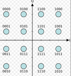
What are we supposed to understand from all these points. and is there a particular way to arrange these points in the constellation.. So i can see from fig 3 that as we keep increasing from 4 to 8 to 16 qam the bit values for each points increase as in 4 qam has 2 bit values... So its in someway a representation of all values but why a circle or sometimes square??? Pls have been trying to understand this and getting little confused... Pls help... Thank you!!!
1)What is it?
2)When does it occur?
3)why is it used?
4)What do we understand from it?
Is it used for particular process like modulation or for any other purpose or in general for all communication systems???
I read once to design a good system we need to have the constellation diagram well so we can see how effiecient the communication will be.


What are we supposed to understand from all these points. and is there a particular way to arrange these points in the constellation.. So i can see from fig 3 that as we keep increasing from 4 to 8 to 16 qam the bit values for each points increase as in 4 qam has 2 bit values... So its in someway a representation of all values but why a circle or sometimes square??? Pls have been trying to understand this and getting little confused... Pls help... Thank you!!!
Last edited: